5-2
5-2 TRANSMITTER CIRCUITS
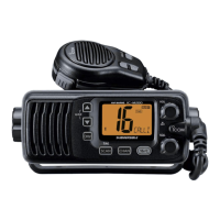
TX AF CIRCUITS
The AF signal from the microphone (MIC signals) is passed
through the MIC mute SW (IC260A), amplified by MIC AMP
(IC200B), and then applied to the D/A converter (IC190),
through another MIC mute SW (IC260C).
The level-adjusted MIC signal is pre-emphasized by R201
and C385 to obtain +6 dB/octave of frequency response,
and then passed through the limiter (IC200A) to prevent
over deviation. The amplitude-limited MIC signal is filtered by
the splatter filter (IC200D), which removes 3 kHz and higher
signals, and then applied to the VCO (Q21, Q22, D22 and
D23) for frequency modulation.
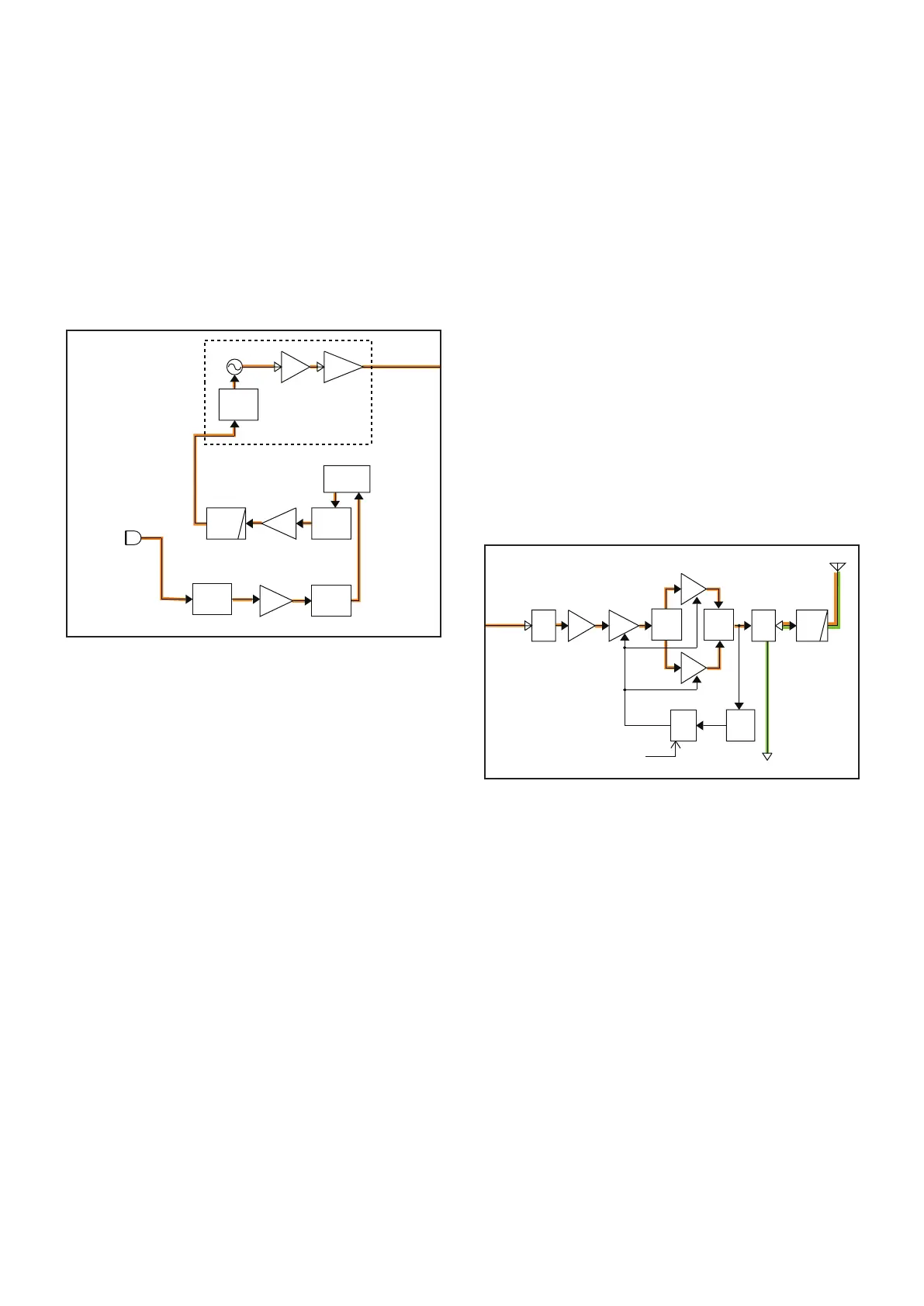
TX AMPLIFIERS
The frequency-modulated signal from the VCO (Q21, Q22,
D22 and D23) is passed through the buffers (Q23 and Q24)
and LO SW (D50), and then sequentially amplified by the
buffer AMP (Q50) and pre-drive AMP (Q53).
The amplified signal is splitted by the power splitter (L100,
L101, R463, C445 and C446) and applied to the power
AMPs (Q54 and Q55). The amplified signals are combined
at the power combiner (L107, L108, R465, C457 and C458)
to obtain the TX output power.
The amplified TX signal is passed through the ANT SW
(D52) and LPF (L81, L82, C83–C86 and C89), and then
applied to the antenna.
APC CIRCUIT
A portion of TX output signal is rectified by D91 to produce
the DC voltage which represents the TX power level.
The APC AMP (IC50) compares the voltage and TX power
setting voltage from the D/A converter (IC190). The resulted
voltage from the APC AMP controls the gain of both driver
AMP (Q53) and power AMPs (Q54 and Q55), to keep the TX
output power constant.
• TX AF AND MODULATION CIRCUITS
LPF
ANT
SW
ANTENNA
PWR
AMP
DRIVE
PRE
LO
SW
BUFF
From the VCO
To LO switch
APC
CTRL
BUFFBUFF
LPF
LIMI
T
AM P
MIC
AMP
MIC
MUTE
MIC
MUT E
Receive circuits
D52,D90
Q53
Q54
PWR
AMP
Q55
D50
Q50
Q24
Q23
Q 21,Q22
PWR
DET
MOD
MUT E
PRE
ENPHA
D/A
VCO
D91
Q20
IC50
IC190
IC200A
IC200D
IC200B
MIC
PWR
SPLITTER
PWR
COMBINER
D20
D
21
D22,D23
INMIC
MOD
IC260A
IC260C
MC250
Q357
PCON
LPF
ANT
SW
ANTENNA
PWR
AMP
DRIVE
PRE
LO
SW
BUFF
From the VCO
To LO switch
APC
CTRL
BUFFBUFF
LPF
LIMI
T
AM P
MIC
AMP
MIC
MUTE
MIC
MUT E
Receive circuits
D52,D90
Q53
Q54
PWR
AMP
Q55
D50
Q50
Q24
Q23
Q 21,Q22
PWR
DET
MOD
MUT E
PRE
ENPHA
D/A
VCO
D91
Q20
IC50
IC190
IC200A
IC200D
IC200B
MIC
PWR
SPLITTER
PWR
COMBINER
D20
D
21
D22,D23
INMIC
MOD
IC260A
IC260C
MC250
Q357
PCON
• TX AMPLIFIERS AND APC CIRCUIT

 Loading...