6-1
SECTION 6 ADJUSTMENT PROCEDURE
M CONNECTION
EQUIPMENT GRADE AND RANGE EQUIPMENT GRADE AND RANGE
Cloning software
ADJ-M25/M25EURO (Revision 1.0 or later)
Cables OPC-478UC and OPC-1655
RF power meter
(50
Ω
terminated)
Measuring range: 0.1–6 W
Frequency range: 100–300 MHz
SWR: Less than 1.2 : 1
Frequency counter
Frequency range: 0.1–300 MHz
Frequency accuracy: ±1 ppm or better
Input level: Less than 1 mW
Standard signal
generator (SSG)
Frequency range: 0.1–300 MHz
Output level: –20 dBµ to 90 dBµ
(–127 to –17 dBm)
M REQUIRED EQUIPMENTS
6-1 PREPARATION
• JIG CABLES
JIG <OPC-1122U/UC>
JIG <OPC-966U (Multi-connector)>
OPC-478/U/UC
WHITE (MIC)
(MIC line)
(SP line)
BLUE (CLONE)
SHIELD (GND)
(CLONE line)
OPC-1668
To the transceiver
RED (AFOUT)
To audio generator/AC millivoltmeter
To SINAD meter/speaker
33 k
Ω
PTT
Add a jumper wire here
OPC-966U
(USB type Cloning cable)
+
GND
MIC
PTT
GND
GND
SP
PTT
+−
AC MILLIVOLTMETER
(10 mV to 10 V)
AUDIO GENERATOR
(300–3000 Hz/1–500 mV)
+−
+−
4.7 µF
EXT. SPEAKER
(1 W/8 Ω)
PTT
+
MICE
MIC
PTT
PTTE
Add a jumper wire here
OPC-966
(RS-232C type Cloning cable)
AUDIO GENERATOR
(300–3000 Hz/1–500 mV)
+−
+−
AC
MILLIVOLT-
METER
(10 mV to 10 V)
4.7 µF
GND
SP
+−
EXT. SPEAKER
(1 W/8 Ω)
(CLONE)
(GND)
(SP)
+−
AC
MILLIVOLTMETER
(10 mV to 10 V)
AUDIO GENERATOR
(300–3000 Hz/1–500 mV)
+−
+
4.7 µF
EXT. SPEAKER
(? W/? Ω)
+
−
SETTING;
Frequency : 1 kHz
Level : ?? mVrms
Waveform : Sine wave
Fuses
5 A
DC power supply
(3.7 V/5 A)
⊕
−
⊕
−
LOCK VOLTAGE
REFERENCE FREQUENCY
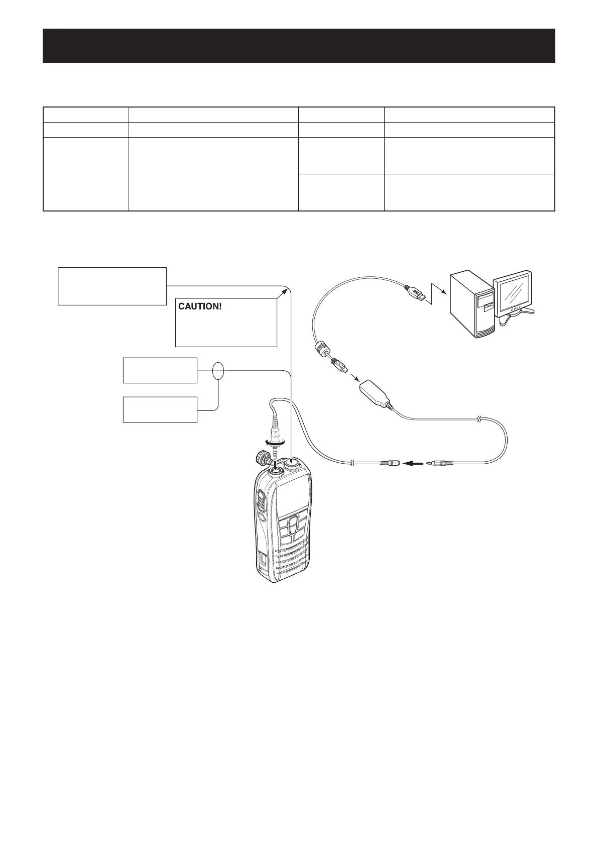
GENERAL CONNECTION
GENERAL CONNECTION
TX POWER
DEVIATION
MOD. BALANCE
CTCSS/TONE
SENSITIVITY
S-METER
SQUELCH
SINAD meter
Speaker (8 Ω)
to the antenna connector
RF power meter
0.1–6 W/50 Ω
Frequency
counter
Standard signal generator
–20 to 90 dBµ
(–127 dBm to –17 dBm)
DO NOT transmit while
an SSG is connected to
the antenna connector.
To [SP/MIC]
PC
to USB port
OPC-478UC
(USB type)
Modified
OPC-1655

 Loading...