6-2
ADJUSTMENT CONDITION
REFERENCE FREQUENCY
TX OUTPUT POWER
FM MODULATION
RX SENSITIVITY
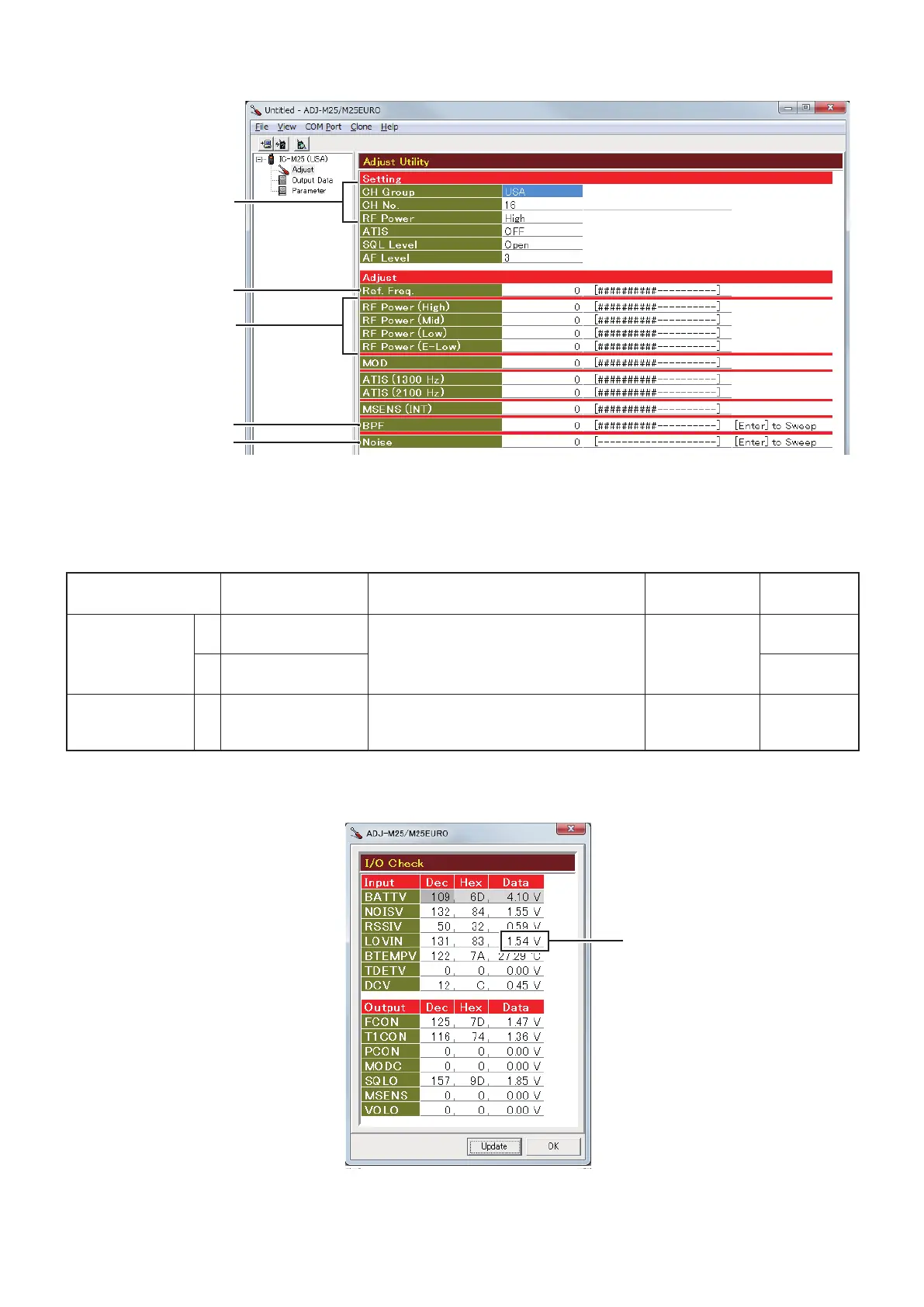
• I/O Check screen
(The values shown above are exsample only.
Each transceiver has own values.)
The Lock Voltage is displayed here.
SQUELCH
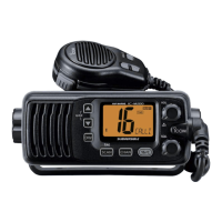
M ADJUSTMENT UTILITY SCREEN
ADJUSTMENT
TRANSCEIVER’S
CONDITION
OPERATION
ADJUSTMENT
ITEM
VALUE
PLL LOCK
VOLTAGE
VERIFICATION
1 • CH.: 16
• Receiving
1) Connect an RF power meter to the
antenna connector.
2) Click the [Update (F5)] button to check on
the "I/O Check screen" as below.
[LVIN]
(On the "I/O
Check screen")
1.65 V ±0.5 V
2 • CH.: 16
• Transmitting
1.70 V ±0.5 V
REFERENCE
FREQUENCY
1 • CH.: 16
• Transmitting
• Loosely couple a frequency counter to the
antenna connector. [Ref. Freq.]
156.800000
MHz
(±500 Hz)
6-2 FREQUENCY ADJUSTMENTS
1) Select an adjustment item using [
↑
]/[
↓
] on the PC's keyboard.
2) Set or modify the adjustment value as specified using [
←
]/[
→
] on the PC's keyboard, and then push [ENTER].
ADJUSTMENT CONDITION
REFERENCE FREQUENCY
TX OUTPUT POWER
FM MODULATION
RX SENSITIVITY
• I/O Check screen
(The values shown above are exsample only.
Each transceiver has own values.)
The Lock Voltage is displayed here.
SQUELCH

 Loading...