26
10
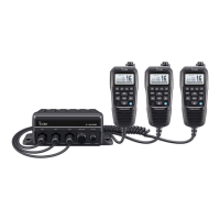
HM-127 REMOTE-CONTROL MICROPHONE
■ Panel description
The optional HM-127 remotely controls the IC-M402 and pro-
vides an optional intercom function.
q POWER SWITCH [PWR] (p. 29)
Push for 2 sec. to turn the HM-127 power ON or OFF
when the IC-M402 power is turned ON.
w PTT SWITCH [PTT] (pgs. 6, 29)
Push and hold to transmit; release to receive.
e CHANNEL UP/DOWN SWITCHES [
YY
]/[
ZZ
]
➥ Push either switch to change the operating channel, set
mode contents, etc. (pgs. 6, 29)
➥ While pushing [H/L], push [Y]/[Z] to adjust the bright-
ness of the LCD and switch backlight. (p. 32)
➥ Push either switch to adjust audio level or noise squelch
level after [VOL] or [SQL] is pushed, respectively.
(pgs. 20, 29)
➥ In set mode, changes setting of the selected item.
(pgs. 20, 34)
➥ Checks tag channels or changes scanning direction dur-
ing scan. (pgs. 9, 33)
r CHANNEL 16/CALL CHANNEL SWITCH [16•9]
➥ Selects Ch 16 when pushed. (pgs. 5, 31)
➥ Selects call channel when pushed for 1 sec. (pgs. 3, 31)
•“CALL” appears when call channel is selected.
➥ Push for 3 sec. to enter call channel programming con-
dition when call channel is selected. (pgs. 7, 32)
➥ While pushing [H/L], enters memory name programming
condition. (pgs. 7, 35)
➥ Enters set mode when pushed and hold [16•9] turning
the power ON. (pgs. 20, 34)
 Loading...