TM 10-7360-226-13&P
CONTAINERIZED KITCHEN (CK) 0006 00
OPERATION UNDER USUAL CONDITIONS
0006 00-18
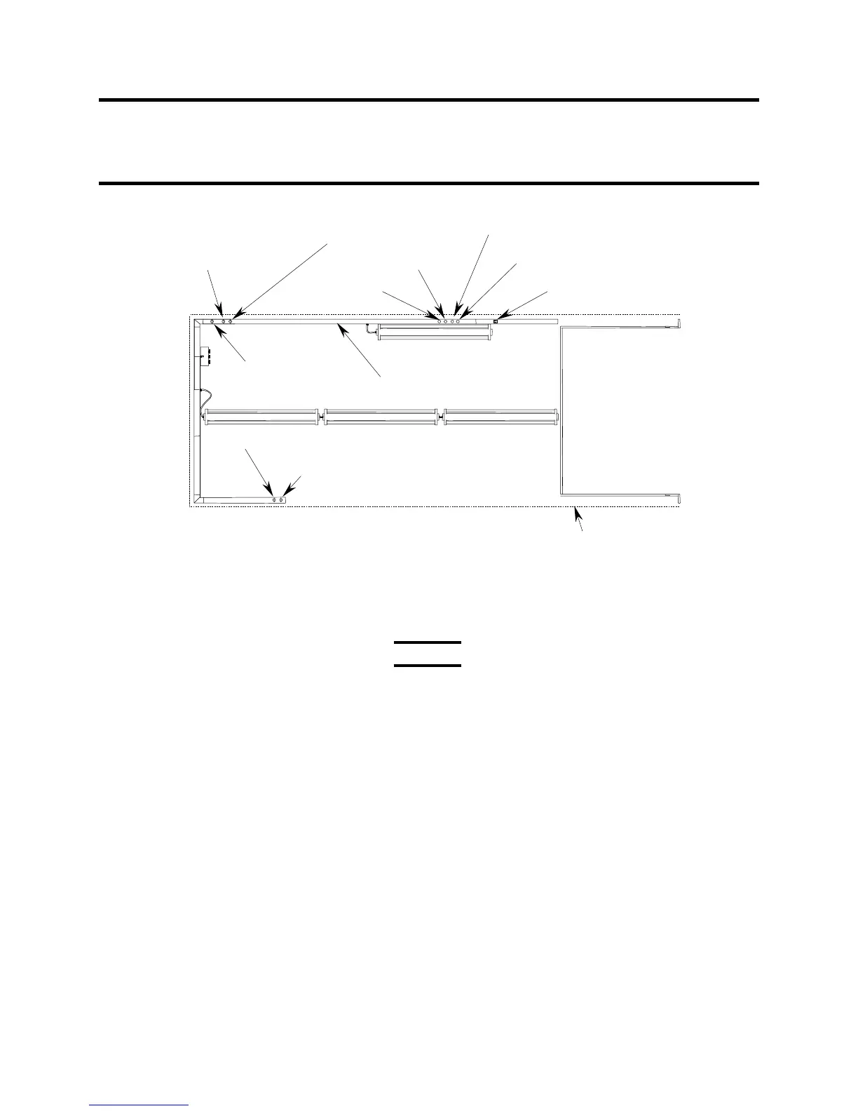
FOOD PREPARATION AREA
SERVING AREA
SHELTER CORE
(TOP VIEW)
WHITE LIGHT
WHITE LIGHT
BLACKOUT LIGHT
OVEN ASSY 24 VDC
WHITE LIGHT
BLACKOUT LIGHT
APPLIANCE CONTROL BOX
MECHANICAL
ROOM
MOBILE
WARMING
CABINET
REFRIGERATOR 1
REFRIGERATOR 2
CEILING RACEWAY
Figure 13. Ceiling Raceway Electrical Connections.
Use caution when moving appliances and equipment in the following
steps, to avoid pinching hands or fingers.
1. Unstrap the sink assembly and move it to approximately its operational position under the
window nearest the personnel door in the food preparation wing.
2. Unstrap the two mobile storage cabinets and move them to the serving wing.
3. Remove the water supply and drain hoses from the lower shelf and back of the sink
assembly.
4. At the back of the sink assembly, attach one end of the 15-foot internal drain hose to the
sink drain and the other end to the fitting on the floor drain by the personnel door. Route the
hose close to the walls.
5. Remove the dust cap from the exterior drain fitting at the base of the shelter, to the left of
the personnel door. Attach the 50-foot external drain hose to the fitting. Attach the other
end to the water collection facility.
6. From outside, feed the male end of the water supply hose though the smaller of the two
penetrations below the window in the food preparation wing. Ensure that the hose washer
on the sink fitting is in place. Connect the hose to the fitting. Connect the other end of the
hose to the water source.
WARNING