20
7
CONNECTIONS
AND
INSTALLATION
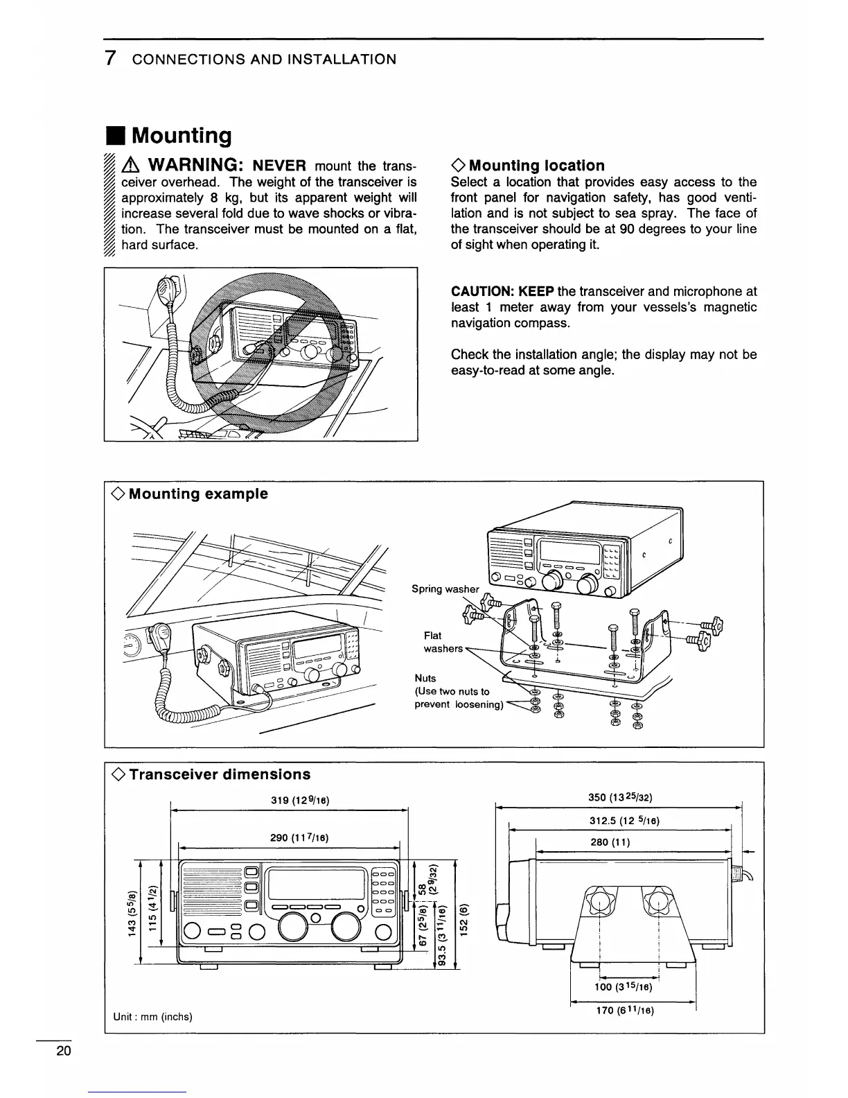
• Mounting
~
~
Lh
WARNING:
NEVER
mount the trans-
~
ceiver overhead. The weight of the transceiver is
~
approximately 8
kg,
but its apparent weight will
~
increase several fold due to wave shocks or vibra-
~
tion. The transceiver must
be
mounted
on
a flat,
~
hard surface.
~
0 Mounting example
Flat
()Mounting
location
Select a location that provides easy access to the
front panel for navigation safety, has good venti-
lation and is not subject to sea spray. The face of
the transceiver should
be
at 90 degrees to your line
of sight when operating
it.
CAUTION: KEEP the transceiver
and
microphone at
least 1 meter away from your vessels's magnetic
navigation compass.
Check the installation angle; the. display may not
be
easy-to-read at some angle.
washers
""---111----,.~
0 Transceiver dimensions
319 (129/16)
290 (117/16)
~
!i
It)
~
"'
10
-
"""
-
-
Unit : mm (inchs)
Nuts
(Use two nuts to
prevent
loosening)
t
~
DI)C\1
10~
~
0
~
"'
C\1
~
-
10
,.._
~
-
co
10
<'?
(l)
350 (13 25/32)
312.5 (12
5/16)
280 (11)
170 (611/16)