4-4 OTHER CIRCUIT
4-4-1 VOX CIRCUIT (MAIN UNIT)
The VOX circuit toggles TX and RX automatically by detect-
ing voice signals from the microphone.
The MIC signals from the external microphone are applied
to the VOX amplifier (IC431, pins 1, 2). The amplified MIC
signals are applied to another VOX amplifier (IC431, pin 5),
and the amplified MIC signals are output from pin 7, then
rectified by D430. The rectified signal is applied to the CPU
(IC360, pin 29) as "VOXT" signal which turns the transmit
circuits ON. Then the CPU outputs "VOXM" signal from pin
117 to the AF mute switch (IC430, pin 5) to turn the AF
mute switch OFF, and the MIC signals are applied to the
pre-emphasis circuit.
4 - 4
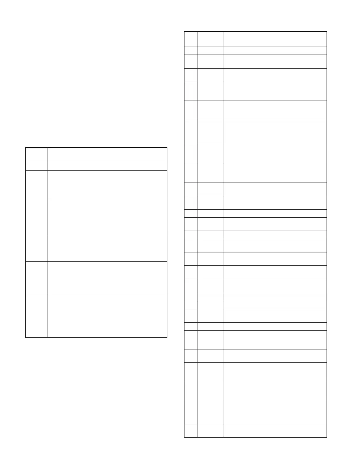
Pin
No.
Port
Name
Description
1 BEEP Outputs beep sound to the AF circuits.
4
DASTB
(DAST)
Outputs strobe signal to the D/A converter (RF
UNIT; IC190, pin 6).
5
PLSTB
(PLST)
Outputs PLL strobe signal to the PLL IC (RF
UNIT; IC1, pin 3).
11
SCLK
(SCK)
Outputs serial crock signal to the PLL IC (RF
UNIT; IC1, pin 4), D/A converter (RF UNIT;
IC190, pin 7).
12 V5VS
Outputs V5V regulator (Q220) control signal.
"High"= While power save mode (The VCO
(Q21, Q22, D21−D23) is not activated).
13 T5VS
Outputs T5V regulator (RF UNIT; Q222) control
signal.
"Low"= While transmitting.
"High"= While receiving or power save mode.
14 LCDS
Outputs LCD contrast select signal.
"Low"= While "Bright" is selected.
"High"= While "Dark" is selected.
15 LEDS
Outputs backlight LED (DS240
−
DS243, DS250
−
DS253) control signal to the LED driver (Q240).
"High"= While the backlight is ON.
25 RES
Input port for reset signal from the reset IC
(IC341, pin 1).
27
†
WDECV
Input port for demodulated weather alart (WX)
signal from the AF circuits.
28 EXDET Input port for external connect detect signal.
29 VOXT
Input port for audio detect signal from the VOX
amplifi er (IC431, pin 7) for the VOX operation.
30 BATTV Input port for remaining battery power.
31 TDETV
Input port for power level detect signal from the
transmit power detector (RF UNIT; D80).
32 NOISV
Inputo port for the noise level from the FM IF IC
(IC170, pin 14).
33 RSSIV
Input port for RSSI signal from the FM IF IC
(IC170, pin 12).
34 LOINV
Input port for VCO (
Q21, Q22, D21−D23
) lock
voltage.
35 TEMPV Input port for temperture detection.
36 WET Input port for leaking detection signal.
93 ESCK
Outputs serial crock signal to the EEPROM
(IC340, pin 6).
94 ESDA Outputs serial data to the EEPROM (IC340, pin 5).
95 R5VS
Output R5V line control signal to the R5V
regulator (Q221).
"High"= While receiving.
96 EXPTT
Input port for external PTT switch.
"High"= While the external PTT switch is pushed.
97 TXMS
Outputs transmit mute signal to the transmit
mute switch (Q351).
"High"= While transmitting.
98 DETMS
Outputs mute signal to the AF mute switch
(IC260, pin 13).
"High"= While the squelch is open.
100 AFVS
Outputs AF power amplifier power supply
switch control signal.
"High"= While the audio is emitted from the internal
speaker (CHASSIS; SP1) or external speaker.
102 PTTIN
Input port for [PTT] switch. (RF UNIT; S250)
"High": While [PTT] switch is pushed.
Line
name
Description
VCC The same voltage as attached battery pack.
CPU5V
Common 5 V converted from VCC line at the
CPU5V regulator (IC220).
The converted voltage is applied to the CPU
(IC360), Reset IC (IC341), EEPROM (IC340), etc.
5V
Common 5 V converted from VCC line at the 5V
regulator (Q223−Q225) controlled by "M5VS" signal
from CPU (IC360, pin 101).
The converted voltage is applied to the backlight
LED'S (DS240−DS243, DS250−DS253), D/A con-
verter (RF UNIT; IC190), PLL IC (RF UNIT; IC1), etc.
V5V
Common 5 V converted from VCC line at the V5V
regulator (RF UNIT; Q220).
The converted voltage is applied to the VCO (RF
UNIT; Q21, Q22, D21−D23)
R5V
Receive 5 V controlled by R5V regulator (Q221)
using "R5VS" signal from the CPU (IC360, pin 95).
The voltage is applied to the receive circuits (RF
UNIT; 1st mixer (Q150), 1st IF amplifier (Q151),
RF amplifi er (Q90), etc.).
T5V
Transmit 5 V controlled by T5V regulator (RF UNIT;
Q222) using "T5VS" signal from the CPU (IC360,
pin 13).
The controlled voltage is applied to the transmit
circuits (RF UNIT; differential amplifi er (IC50), pre-
driver (Q53), power amplifier (Q54), microphone
amplifi er (IC8), etc.).
4-5 POWER SUPPLY CIRCUITS
(MAIN UNIT AND RF UNIT)
4-6 PORT ALLOCATIONS
4-6-1 CPU (MAIN UNIT; IC360)
†
; ([USA], [USA-01] only)