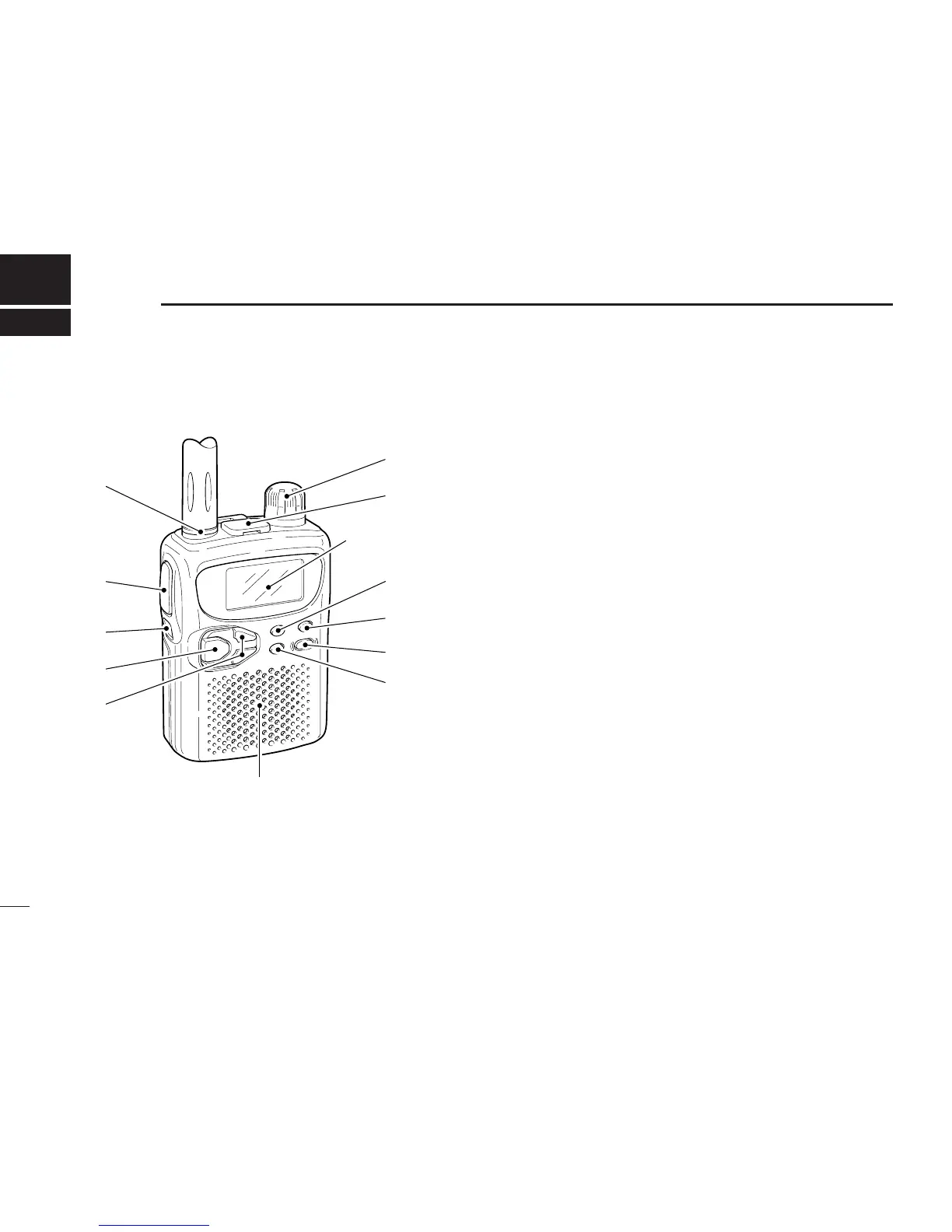
■ Panel description
q ANTENNA CONNECTOR (p. 1)
Connects the supplied antenna.
•An optional AD-92SMA is available for connecting an antenna
with a BNC connector.
w MONITOR SWITCH [SQL] (pgs. 10, 27)
➥Push and hold to temporarily open the squelch and
monitor the operating frequency. (default behaviour)
➥While pushing, rotate the tuning dial to set the squelch
threshold level.
➥Push [FUNC] + [SQL] to toggle the attenuator circuit ON
and OFF.
e FUNCTION SWITCH [FUNC]
While pushing this switch, other switches and tuning dial
perform secondary functions.
•“Push [FUNC] + a switch” means “while pushing the [FUNC]
switch, push the switch.”
r BAND SWITCH [BAND]
➥Push to select the operating band (VHF, UHF, etc.). (p. 6)
•Broadcast band, HF band, 50 MHz band, VHF avionics band,
144 MHz band, 300 MHz band, 400 MHz band, 800 MHz
band and 1200 MHz band can be selected.
•While pushing this switch, rotating [DIAL] also selects the op-
erating band.
➥Transfers the displayed frequency to the VFO in mem-
ory mode. (p. 6)
➥Push [FUNC] + [BAND] to enter the scan edge set mode
in VFO mode. (p. 17)
➥Push [FUNC] + [BAND] to enter the bank scan set mode
in memory mode. (p. 16)
2
2
PANEL DESCRIPTION