4 - 4
(3) AM MODE
The 3rd IF signal is output from the FM IF IC (IC2, pin 3),
and passes through the mode switch (D109) and ceramic
bandpass filter (FI2). The filtered signal passes through the
mode switch (D112), and is then applied to the IF amplifier
(Q531). The amplified signal is demodulated at the AM
detector (Q4). The AF signals pass through the ANL circuit
(D114), and are then applied to the AF switch (IC12, pin 4)
via the “A_DETAM” line, and are then applied to the AF cir-
cuit (LOGIC unit) as “A_DET” signal.
(4) SSB/CW MODES
The 3rd IF signal is output from the FM IF IC (IC2, pin 3),
and passes through the mode switch (D110) and ceramic
bandpass filter (FI6). The filtered signal passes through the
mode switch (D113), and is then applied to the IF amplifier
(Q531). The amplified signal is mixed with BFO signal from
the LOGIC unit at the mixer (D115 and D116) to demodulate
to AF signals. The AF signals are applied to the SSB AF
amplifier (Q532), and are then applied to the AF switch
(IC12, pin 1) via the “A_DETSSB” line, and are then applied
to the AF circuit (LOGIC unit) as “A_DET” signal.
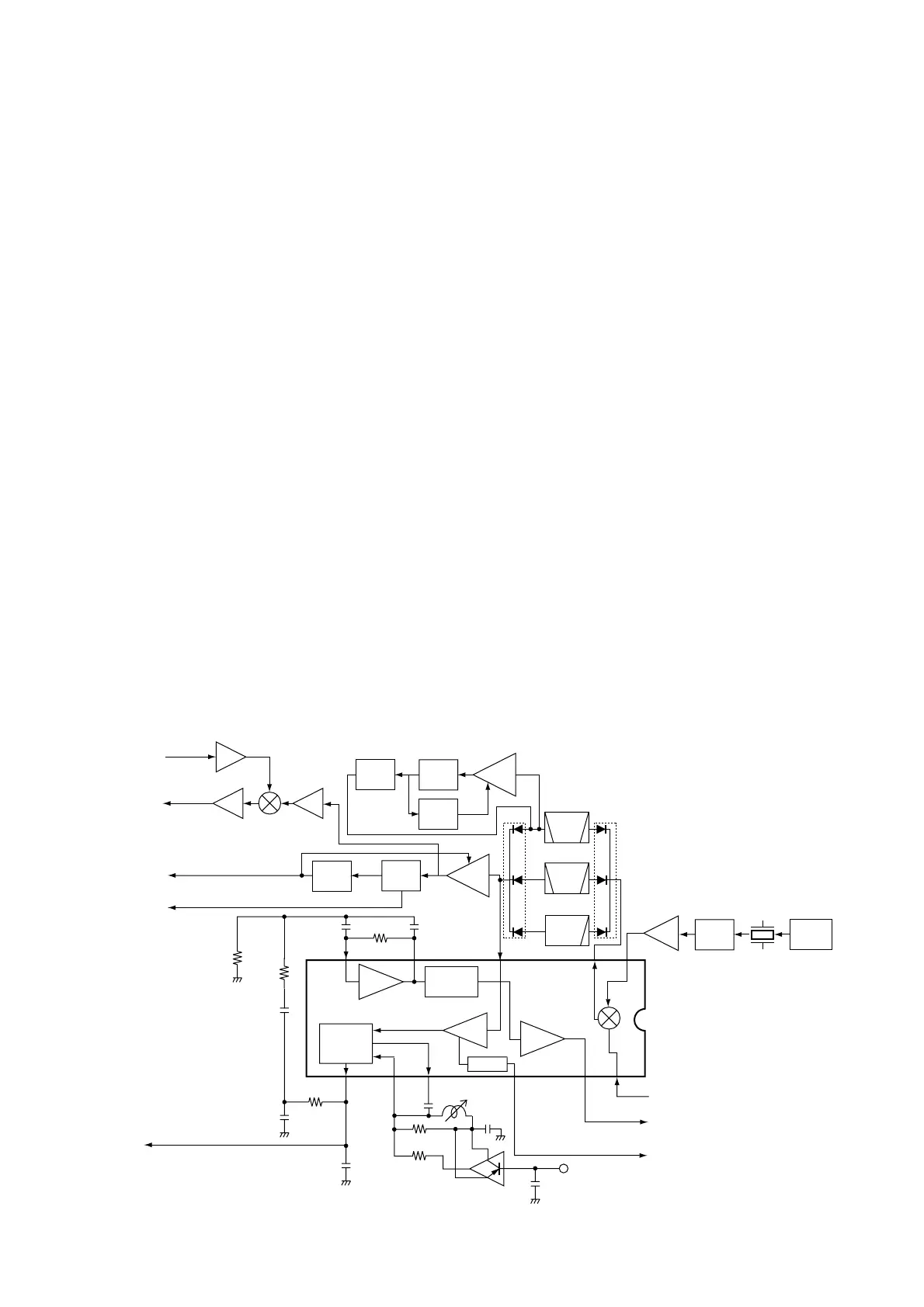
• B-BAND CIRCUIT
The 19.65 MHz 2nd IF signal from the 2nd IF amplifier
(Q542) is applied to the 3rd mixer section of the FM IF IC
(IC17, pin 16) and is then mixed with the 3rd LO signal for
conversion into a 450 kHz 3rd IF signal.
IC17 contains the 3rd mixer, limiter amplifier, quadrature
detector and S-meter detector, etc. A frequency from the
PLL reference oscillator is used for the 3rd LO signal (19.20
MHz).
(1) FM MODE
The 3rd IF signal is output from the FM IF IC (IC17, pin 3),
and passes through the mode switch (D134) and ceramic
bandpass filter (FI8). The filtered signal passes through the
mode switch (D136), and is then fed back and amplified at
the limiter amplifier section (pin 5). The signal is demodulat-
ed AF signals at the quadrature detector section (pins 10,
11) and detector coil (L105). The demodulated AF signals
are output from pin 9 and are applied to the AF switch (IC21,
pin 1) via the “DET_OUT” line, and are then applied to the
AF circuit (LOGIC unit) as “B_DET” signal.
(2) WFM MODE
The 3rd IF signal is output from the FM IF IC (IC17, pin 3),
and passes through the mode switch (D135) and low-pass
filter (L106, C781 and C782). The filtered signal passes
through the mode switch (D137), and is then fed back to the
limiter amplifier section (pin 5). The amplified signal is
demodulated at the quadrature detector section (pins 10 and
11) and detector coil (L105). The AF signals are output from
pin 9 and are applied to the AF switch (IC21, pin 1) via the
“DET_OUT” line, and are then applied to the AF circuit
(LOGIC unit) as “B_DET” signal.
By connecting R436 to R437 in parallel, the output charac-
teristics of pin 12, “RSSI”, change gradually. Therefore, the
FM IF IC can detect WFM components.

 Loading...