4 - 5
(3) AM MODE
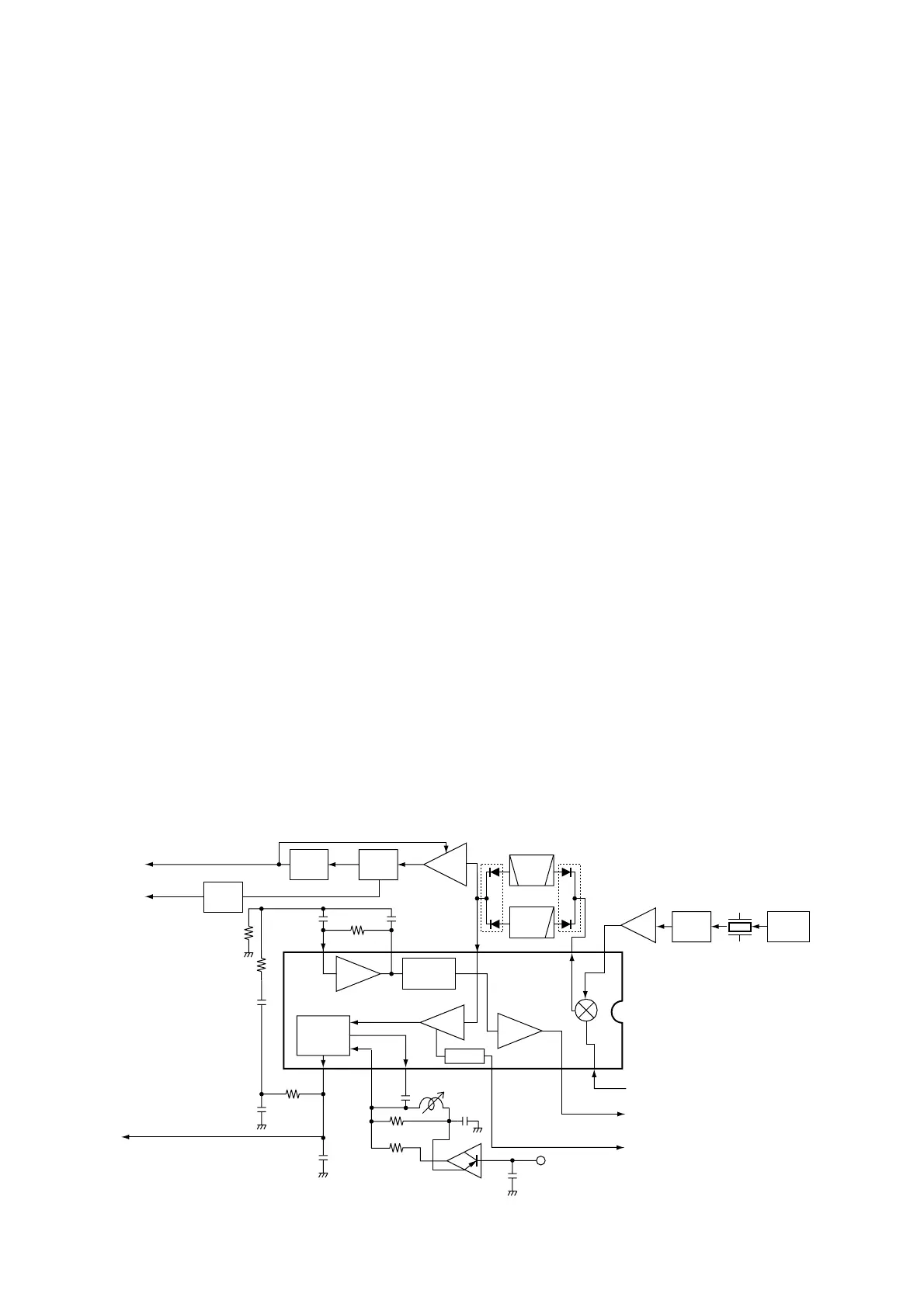
The 3rd IF signal is output from the FM IF IC (IC17, pin 3),
and passes through the mode switch (D134) and ceramic
bandpass filter (FI8). The filtered signal passes through the
mode switch (D136), and is then applied to the IF amplifier
(Q544). The amplified signal is demodulated at the AM
detector (Q545). The AF signals pass through the ANL cir-
cuit (D139), and are then applied to the AF switch (IC21, pin
4) via the “AM_DET” line, and are then applied to the AF cir-
cuit (LOGIC unit) as “B_DET” signal.
4-1-7 AF AMPLIFIER CIRCUIT (LOGIC UNIT)
The AF amplifier circuit amplifies the demodulated AF sig-
nals to drive a speaker.
• A-BAND CIRCUIT
While in FM mode, AF signals from the demodulator circuit
(RF unit) pass through the AF filter (Q25), and are then
amplified at the AF amplifier (Q23).
While in WFM/AM/SSB/CW modes, AF signals from the
demodulator circuit (RF unit) bypass the AF filter via the AF
filter bypass switch (Q26), and are then amplified at the AF
amplifier (Q23).
The signals are applied to the electronics volume (IC7, pin
6) to control volume level. The signals output from pin 5, and
are applied to the pre-amplifier (Q12). The signals are ampli-
fied at the AF amplifier (IC5, pin 1), and then output from pin
6. The signals are applied to the internal speaker which is
connected with J8 via the external speaker jack (J3).
• B-BAND CIRCUIT
While in FM mode, AF signals from the demodulator circuit
(RF unit) pass through the AF filter (Q24), and are then
amplified at the AF amplifier (Q22).
While in WFM/AM modes, AF signals from the demodulator
circuit (RF unit) bypass the AF filter via the AF filter bypass
switch (Q27), and are then amplified at the AF amplifier
(Q22).
The signals are applied to the electronics volume (IC7, pin
11) to control volume level after passing through the mute
switch (Q19). The signals output from pin 12, and are
applied to the pre-amplifier (Q16). The signals are amplified
at the AF amplifier (IC5, pin 1), and then output from pin 6.
The signals are applied to the internal speaker which is con-
nected with J8 via the external speaker jack (J3).
The electronic volume control circuit controls AF gain, there-
fore, the AF output level is according to the [VOL] setting
and also the squelch conditions.
4-1-8 SQUELCH CIRCUIT (LOGIC AND RF UNITS)
• NOISE SQUELCH
The noise squelch circuit cuts out AF signals when no RF
signals are received. By detecting noise components in the
AF signals, the squelch circuit switches the AF mute switch.
A portion of the “A_NOISE” signals from the FM IF IC (RF
unit; IC2, pin 13) are applied to the CPU (LOGIC unit; IC3,
pin 5). The CPU analyzes the noise condition and outputs
the “AFON” signal (from pin 17) to the AF amplifier’s con-
troller (LOGIC unit; Q7).
• TONE SQUELCH
The tone squelch circuit detects AF signals and opens the
squelch only when receiving a signal containing a matching
subaudible tone (CTCSS). When tone squelch is in use, and
a signal with a mismatched or no subaudible tone is
received, the tone squelch circuit mutes the AF signals even
when noise squelch is open.

 Loading...