(a)
Y1--+
D80-D83
(KEYBOARD,
MEMORY-CH
ENTER)
Following is a matrix
for
the KEYBOARD, MEMORY-
CH
ENTER and the optional
RC-12
WIRELESS
REMOTE CONTROLLER.
~
DBO
DB1
DB2 DB3
HEX
y
CODE
1 H L
L
L 1
2 L H L L
2
3 H H L L
3
4 L L H L 4
5 H L H
L 5
6
L H H
L 6
7 H H H
L 7
8 L L L H
8
9 H L L H
9
0 L H L H A
*1
MEMORYCH
ENTER
H H L H B
•
L L H
H c
ENT H L H H D
*2
CE
L H
H H E
*1:
Used in [MEMORY CH] CONTROL.
*2:
Used in the optional
RC-12
WIRELESS REMOTE
CONTROLLER.
Table 5
(b) Y1--+ D84 (DIAL UP/DOWN)
When a TUNING CONTROL
clock
signal is input, the
following results
will
occur.
Y1--+
084
RESULT
H
The receive frequency inceases.
L The receive frequency decreases.
Table 6
(c)
Y1
--+
D85-
7 [TS]
This matrix sets frequency steps.
~
DB5 DB6 DB7
T
0.1
kHz L L L
1kHz
H L L
5kHz L
H L
10kHz
H
H L
12.5kHz
L
L H
25kHz H
L H
Table 7
(d) Y3--+
DB0-1
(FREQUENCY UP/DOWN)
This matrix increments receive frequencies
for
the
optional
RC-12
WIRELESS REMOTE CONTROLLER.
(e) Y3--+ DB2 (SQUELCH STOP)
This matrix stops the scan when the squelch opens.
(f)
Y4--+
D86-7
[SCAN·DELAY]
This matrix sets the scan delay time.
~
DB6 DB7
G
OFF H L
5
(seconds)
L H
15
(seconds)
H H
oo (infinity) L
L
Table 8
(g)
Y6
--+
DB0-4
(Cl·V ADDRESS)
This matrix sets the address
for
the *Cl-V. The
desired address for
IC-R7000 may
be
1
to
31
and
consists
of
5 bits.
*Cl-V: ICOM Communication lnterface-V.
(h)
Y6
--+
DB5
(Cl·V TRANSCEIVE)
This matrix sets the transceive operation
for
the Cl-V.
(i)
Y6--+
DB6-7
(Cl·V BAUD RATE)
This matrix sets the baud rate.
~
DB6
T
76800
L
9600
H
1200 L
300
H
Table 9
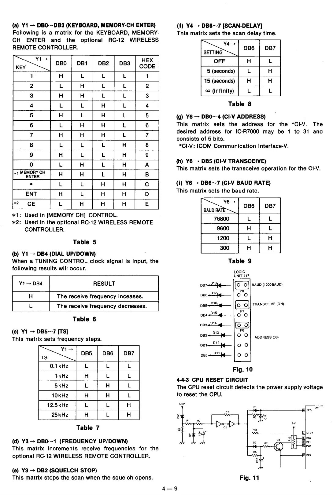
LOGIC
UNIT
J17
DB7
L
L
H
H
DB7•D181'4111
DB6
•D171'411!
DB5
•D161'4111
DB4
,D151'411!
DB3
,D141'4111
DB2
•
D13
1'4111
DB1
•
D121'4111
~
BAUD
(1200BAUD)
PS
0 0
~
TRANSCEIVE (ON)
P7
0 0
rBJ
P6
0 0
0 0
DBO
1 D
11
1'4111
0 0
Fig.10
4.4.3
CPU
RESET
CIRCUIT
ADDRESS
(08)
The
CPU
reset
circuit
detects
the power supply voltage
to
reset the
CPU.
13.BV
IC7
Fig.
11
4-9
 Loading...