Two- Stage Multi Position Furnace
Service
Manual
23
440 08 2002 02
Figure 32
Variable Speed Models
D.C. Motor Speed Wires
Wire Color Motor Speed
Blue Common
White Low Heat
Green Circulating
Black High Heat
Yellow Cooling
Brown Dehum. (80%)*
* Function enabled only when energized with cooling
speed. Motor runs at 80% of cooling speed.
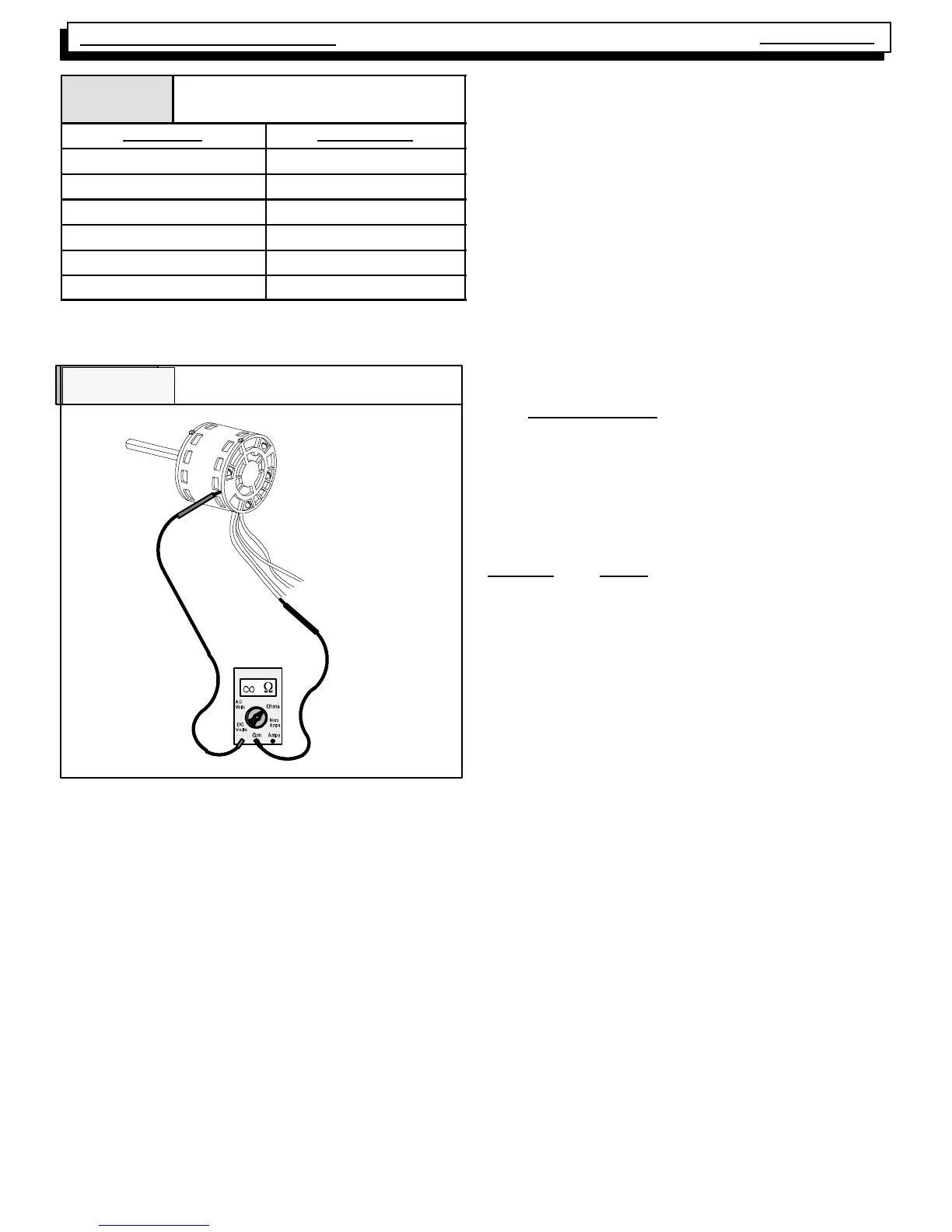
Figure 33
Checking P.S.C. Motor
+
2 Speed Models - P.S.C. Motor
The P.S.C. motor used in 2 speed models may be checked
using traditional Ohmmeter test methods. I.E. Checking
fr om any s peed t ap lead (black , orange, blue, or r ed) to
Neutral (white) should indicate continuity. While checking
from any motor lead to the motor case should indicate in-
finity (no continuity). Before condemning any P. S. C . m ot or
be sure to verify the condition of its capacitor .
SELECTING BLOWER SPEEDS
The wide variet y of applicat ions and inst allat ions of fur-
naces throughout the country makes it impossible to “Fac-
tory Select” blower speeds that will provide proper opera-
tion for all installations. This means then, that the blower
speeds f or bot h heat ing and c ooling mus t be “ F ield Se-
lected” for each particular installation to insure proper op-
eration.
The criteria for selecting the proper blower speeds IS NOT
“High for Cooling, Low for Heating”. Although that may be
how it works out SOMETIMES, It can (in many cases) be
exactly the opposite. (I.E. a Lower speed for Cooling, and
a Higher speed for Heating)
The PROPER CRITERIA FOR SELECTING BLOWER
SPEEDS is as follows:
HEATING
A blower speed must be selected that will provide proper
temperature rise through the furnace. (See “checking tem-
perat ure ris e” f ound on page 9 of t his m anual) . The re-
quired CFM for a particular temperature rise can also be
calculated by using the following formula:
Output BTU
Temp. Rise X 1.08 = CFM
EXAMPLE: Using a 75 Mbt u Non--Condensing f urnace
(equipped with P.S.C. motor)of this series with an output of
60,000 Btuh and a desir ed tem peratur e r ise of 50 _F
(range of 35 --65_F allowable) and a measu red ext ernal
static pressure of 0.2” W.C. while operating on medium--
low speed with a dry coil.
60,000
or 60,000
50 X 1.08 59.4 = 1010 CFM
Checking the blower performance data for this model, (see
Table 7) indicat es t hat @ 0. 2” W.C. E . S. P. medium--low
speed delivers 1030 CF M. A ccordingly, m edium--low
speed is the proper speed to be used in this example for
the HEATING speed.
COOLING
A blower speed must be selected that will provide proper
air flow (Nominal 400 CFM per ton) for the size (capacity)
air conditioning coil being used at the external static pres-
sure of the Duct system (inst allation). This requires
CHECKI NG THE EXT ERNA L S TAT I C P RES SURE , and
then consulting the BLOWER PERFORMANCE DATA to
determine the required speed tap.
EXAMPLE: A 24,000 BTU (2 ton) air conditioning system,
using the same 75,000 BTU furnace as in the previous ex-
ample. The external static pressure is measured with the
unit operating on Low speed, and found to be 0.4” W. C.
with a wet coil.
400 CFM (nominal) per ton required
400 X 2 = 800 CFM required
Checking the blower perfor m ance data (see Table 7)for
this model indic at es that @ 0. 4” W.C. ESP low speed is
delivering 735 CFM. Accordingly, low speed is the proper
speed to be used in this example for the COOLING speed.