Two- Stage Multi Position Furnace
Service
Manual
24
440 08 2002 02
Table 7
Blower Performance Data 75,000
BTUH (PSC Motor)
Air Delivery in Cubic Feet per Minute (CFM)
(Furnace Rated @ 0.5² W.C. ESP)
TAP LOW MED L MED H HIGH
.10 706 917 1163 1368
.20 677 875 1120 1319
sure
.30 636 840 1076 1263
Pres
W.C.
.40 595 812 1031 1202
tatic
sof
.50 546 766 987 1148
al S
nche
.60 490 702 889 1077
xter
I
.70 -- -- -- 630 821 989
E
.80 -- -- -- 550 750 914
.90 -- -- -- 462 676 833
1.0 -- -- -- -- -- -- 601 747
Always check current “Technical Support Manual”
EXTERNAL STATIC PRESSURE (ESP)
External Static Pressure can best be defined as the pres-
sure difference (drop) between the Positive Pressure (dis-
charge) and the Negat ive Press ure (int ak e) sides of the
blower. E xternal St atic Pres sure is developed by the
blower as a result of resistance to airflow (Friction) in the
air distribution system EXTERNAL to the furnace cabinet.
(i.e pressure inside duct)
Resist anc e applied external l y to the furnace (I.E. Duct
work, Coils, Humidifiers, Filters, Etc.) on either the Supply
or Return side of the system, causes an INCREASE in Ex-
ternal Static Pressure, accompanied by a REDUCTION in
airflow.
ESP is affected by two (2) factors.
1. Resistance to Airflow as explained above.
2. Blower Speed. Changing to a higher or lower blower
speed tap will raise or lower the External Static Pres-
sure accordingly.
These effects MUST be understood and taken into consid-
eration when checking ESP/ Airflow to insure that the sys-
tem is operating within design conditions.
Operating a system with Insufficient or Excessive air f low
can cause a variety of different operating problems.
Among these are premat ure heat ing component and/or
compressor failures, reduced capacity, freezing evapora-
tor coils, etc.
System air flow should ALWAYS be verified upon comple-
tion of a new installation, or BEFORE a change--out, heat
exchanger replac ement , or in the case of a compr es sor
failure to insure that the failure was not caused by improp-
er air flow.
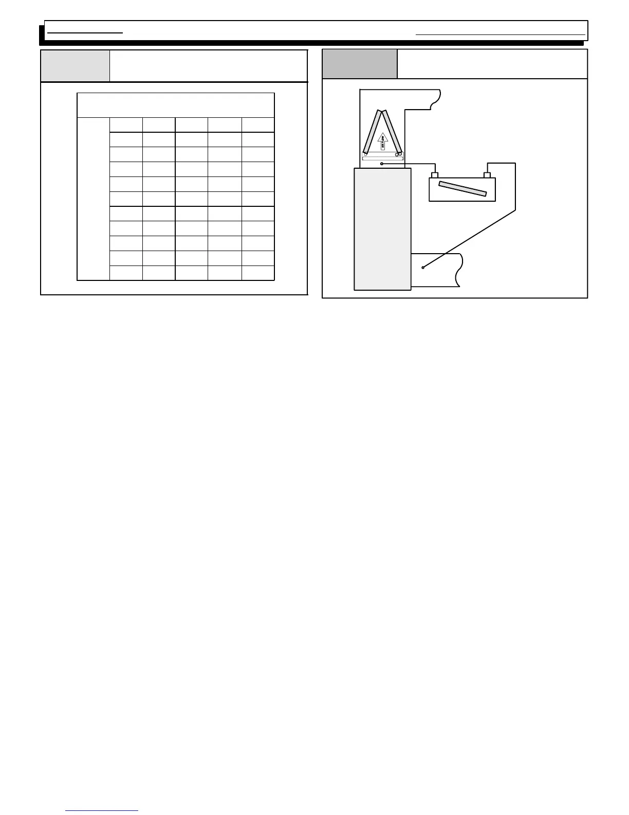
Figure 34
Checking Static Pressure
Supply
Indoor
Section
Inclined
Manometer
Return
CHECKING EXTERNAL STATIC PRESSURE
The air flow through the unit can be determined by measur-
ing the external static pressure of the system, and consulting
the blower performance data for the particular model furnace
you have.
1. Set up to measure ext ernal st at ic press ure at t he sup-
ply and return duct c onnect ions (See F igur e 34) .
2. Drill holes in the ducts for pressure taps, pitot tubes, or
other accurate pressure sensing devices.
3. Connect these taps to a level inclined manometer or
Magnehelic gauge.
4. Ensure the coil and filter are clean, and all the registers
are open.
5. Determine the external static pressure with the blower
operating.
6. Refer to the Air Flow Data for your particular furnace to
find the actual airflow for the current speed tap (or dip
switch setting).
7. If the Actual airflow is either too high, or too low, the
blower speed tap (or dip switch setting) will need to be
changed.
8. Refer to Changing Blower Speeds on the pages that fol-
low for the proper procedure.
9. Select the speed tap (or dip switch setting) that ap-
pears to most closely provide the required air flow for
the system.
10. Recheck the external static pressure with the new
speed tap. External static pressure (and actual air-
flow) will both have changed (either higher, or lower),
depending upon speed tap selected. Recheck the ac-
tual airflow (at this “new” static pressure) to confirm
speed tap selection.
11. Repeat steps 9. and 10. (if necessary) until proper
Speed Tap (and airflow) has been obtained.