Two- Stage Multi Position Furnace
Service
Manual
25
440 08 2002 02
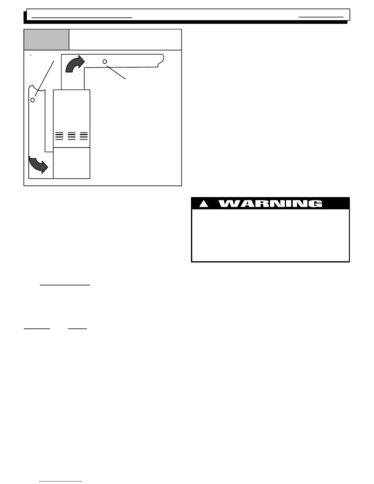
Figure 35
Checking Temperature Rise
Thermometer:
Return Air
Tem p .
Thermometer;
Supply Air Temp.
3¢ min from ra-
diant scene
Return
Supply
Air Flow
Air Flow
CHECKING APPROXIMATE AIR FLOW
If an inclined manomet er or Magnehelic gauge IS NOT
available to c heck t he E xt er nal St at ic P res sur e, OR the
blower performance data is unavailable for your furnace,
approximate air flow canbecalculatedbyMeasuring the
temperature rise, then using the following criteria:
The approximate CFM actually being delivered can be cal-
culated (if the OUTPUT Btu of the furnace is known) by op-
erating the system in HEAT ING, and using the following
formula:
Output BTU
Temp.Risex1.08=CFM
EXAMPLE: Using a (75 Mbtu Input) furnace with an OUT-
PUT of 59,000 Btuh and a measured temperature rise of
50_F.
59,000
or 59,000
50 x 1.08 54 = 1093 CFM
NOTE: This same method can be used (on models
equipped wit h a P. S . C. motor ) t o determine the COOLING
airflow, by TEM PO RA RI LY c onnect ing the c ooling s peed
tap wire to the HEAT terminal of the FAN Control. NEVER
connect two (2) speed tap wires to the same terminal. Do-
ing so will cause motor failure.
VARIABLE SPEED MODELS - D.C. MOTOR
The heating, cooling and circulating blower speeds can be
adjusted by changing the switch settings that are located
on the side of the blower motor (see Figure 36). Switches
#1 and #2 adjust the c irc ulat ing blower speed. Switches
#3, #4 and #5 adjust the heating speeds. Switches #6, #7
and #8 adjust the cooling speed. See the Technical Service
Data Sheet f or t he model y ou are s erv icing to obtain the
switch settings for the desired airflow rates.
CHANGING BLOWER SPEEDS
The procedure for changing blower speeds (if needed) dif-
fers based on whether the unit is a variable speed model,
or a 2 speed m odel.. (See Figure 36 and Figure 38 and
the appropriate sections for the model you are servicing).
Electrical shock hazard.
Turn OFF power to furnace before changing
blower speeds.
Failure to do so can result in personal injury
and/or death.
!
VARIABLE SPEED MODELS - D.C. MOTOR
The heating, cooling and circulating blower speeds can be
adjusted by changing the switch settings that are located
on the side of the blower motor (see Figure 36). Switches
#1 and #2 adjust the c irc ulat ing blower speed. Switches
#3, #4 and #5 adjust the heating speeds. Switches #6, #7
and #8 adjust the cooling speed. See the Technical Service
Data Sheet f or t he model y ou are s erv icing to obtain the
switch settings for the desired airflow rates.