Two- Stage Multi Position Furnace
Service
Manual
26
440 08 2002 02
Blower Motor Control
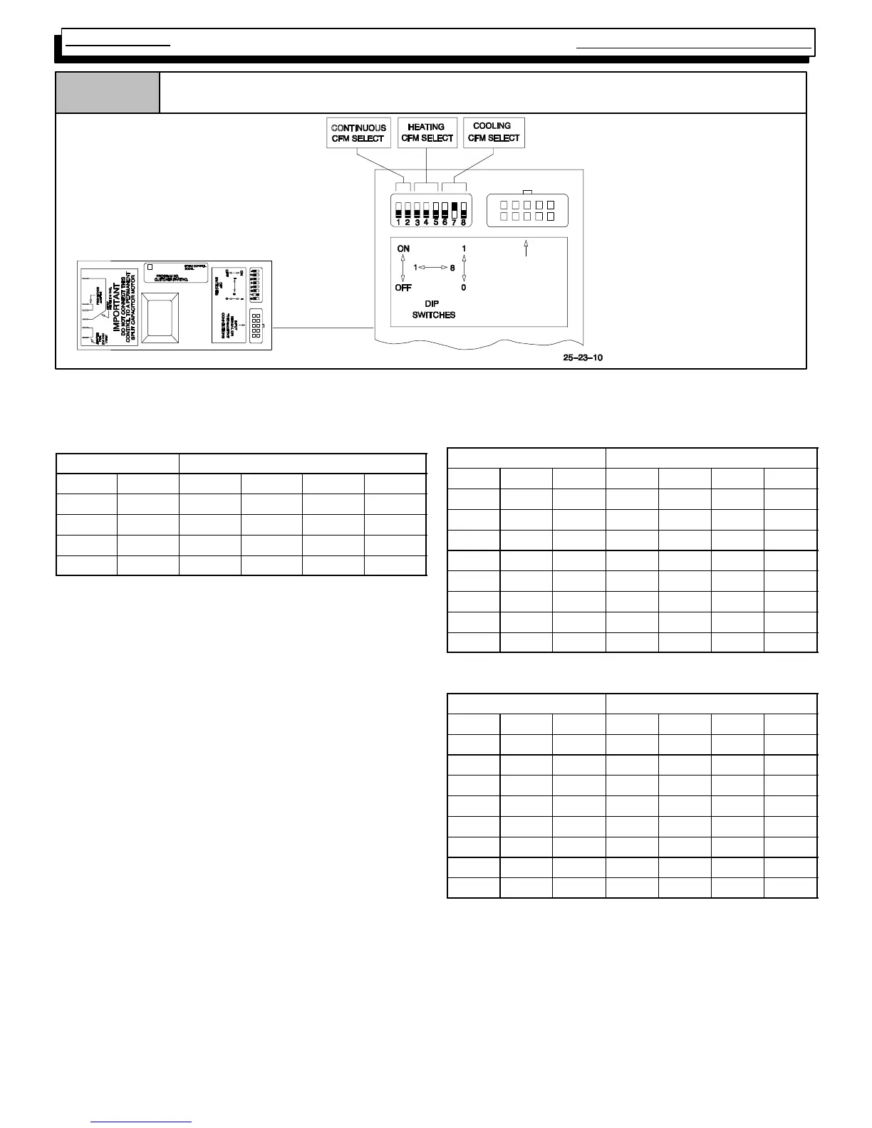
Figure 36
*EXAMPLE
Cooling Airflows Switches
6, 7 & 8:
000 3.5 T on
001 3.0 T on
010 2.5 T on
011 2.0 Ton
*See “Technical Support
Manual” for correct airflow
rates.
010
INPUT
SIGNAL OR
THERMOSTAT
CONNECTIONS
NOTE: Power must be completely OFF to unit any time switch settings are changed or settings will not take effect.
Heating, Cooling & Continuous Airflow Settings
Continuous Blower (CFM) @ 0.10²
²²
² Static
Switch Settings
Furnace Model
#1 #2 50K 75K 100K 125K
0* 0* 540 540 700 703
0 1 660 660 860 821
1 0 780 780 1020 1000
1 1 900 900 1180 1160
*Factory Setting
Lo Heat Air Temperature Adjustment (°
°°
° F)**
Switch Settings
Furnace Model
#3 #4 #5 50K 75K 100K 125K
0** 0** 0** 0 0 0 0
0 0 1 1 1 1 6
0 1 0 4 2 2 8
0 1 1 7 3 5 12
1 0 0 11 6 8 16
1 0 1 -- 7 -- 4 -- 5 -- 1
1 1 0 -- 1 1 -- 6 -- 9 -- 4
1 1 1 -- 1 5 -- 9 -- 1 1 -- 7
*Factory setting
Hi Heat Air Temperature Adjustment (°
°°
° F)**
Switch Settings
Furnace Model
#3 #4 #5 50K 75K 100K 125K
0** 0** 0** 0 0 0 0
0 0 1 3 2 3 2
0 1 0 6 4 5 6
0 1 1 14 6 9 11
1 0 0 17 11 13 13
1 0 1 -- 8 -- 4 -- 4 -- 5
1 1 0 -- 1 3 -- 4 -- 7 -- 5
1 1 1 -- 1 7 -- 4 -- 9 -- 5
*Factory setting
**Approximate air temperature change from factory setting
@0.20² static on high heat ).