10
441 01 2611 06
Requirements
1. Providethespacewithsufficientairforpropercombustionand
ventilation of flue gases using horizontal or vertical ducts or
openings.
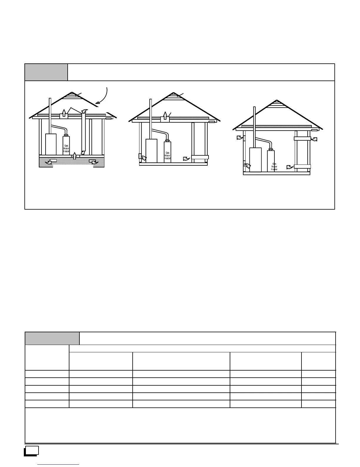
2. Figure 8illustrateshowtoprovidec ombustionandventilation
airwhentwopermanentopenings,oneinletandoneoutlet,are
used.
a. One opening MUST commencewithin12² of the floor
and the s econd opening MUST commencewithin 12² of
the ceiling.
b. Size openings and ducts per Table 1.
Figure 8
Furnace
Furnace
Minimum One Inlet and One Outlet Air Supply is Required
May be in and Combination Shown
Inlet Air Opening Must be Within12²(300mm) of floor
Outlet Air Opening Must be Within12²(300mm) of ceiling
(1) 1 Square Inch (6cm
2
) per 4000 BTUH
(2) 1 Square Inch (6cm
2
) per 2000 BTUH
Outside Air (This is ONLY a guide. Subject to codes of country having jurisdiction.)
This installation NOT approved in Canada
Gas Vent
Gas Vent
Gas Vent
Gable Vent
Gable Vent
Outlet
Air (1)
Outlet Air (1)
Outlet Air (1)
Furnace
Outlet
Air (2)
Optional Inlet Air (1)
Ventilated Attic
Ventilated Attic
Ventilated Crawl Space
Inlet
Air (1)
Inlet
Air (1)
Inlet
Air (1)
Inlet
Air (2)
Inlet
Air (2)
Top Above Insulation
Top Above Insulation
Soffit Vent
Soffit Vent
c. Horizontal duct openings require 1 square inch of free
areaper2,000BTUH(1,100mm
2
/kW)ofcombinedinput
for all gas appliances in the space (see Table 1).
d. Vertical ductopeningsoropenings directlycommunicat-
ing with the outdoors require 1 square inch of free area
per4,000 BTUH(550 mm
2
/kW)for combined input ofall
gas appliances in the space (see Table 1).
3. When one permanent outdoor opening is used, the opening
requires:
a. 1 sq. in of free area per 3,000 BTUH (700 mm
2
/kW) for
combined input of all gas appliances in the space (see
Table 1) and
b. notlessthanthesumoftheareasofallventconnectorsin
the space.
The opening shall commence within 12 ² of the top of the enclo-
sure.Appliancesshallhaveclearancesofatleast1² fromthesides
andback and6² fromthefront.Theopeningshalldirectlycommu-
nicatewiththeoutdoorsorshallcommunicatethroughaverticalor
horizontalducttotheoutdoorsorspaces(crawlorattic)thatfreely
communicate with the outdoors.
4. Combination of Indoor and Outdoor Air shall have:
a. Indoor openings that comply with the Indoor Combus-
tion Air Method below and
b. Outdoor openings located as required in the Outdoor
Combustion Air Method above and
c. Outdoor openings sized as follows.
1) Calculate the Ratio of all Indoor Space volumedivid-
edbyrequiredv olumeforIndoorCombustionAirMeth-
od. Outdoor openings sized as follows.
2) OutdooropeningsizereductionFactoris1minusthe
Ratio in 1) above.
3) Minimum size of Outdoor openings shall be the size
required in Outdoor Combustion Air Method above
multiplied by reduction Factor.
Table 1
Free Area
Minimum Free Area Required for Each Opening or Duct to Outdoors
Input
Rating
Two HorizontalDucts
(sq. in./2,000 BTUH)
Single Opening
(sq. in./3,000 BTUH)
Two VerticalDucts or Openings
(sq. in./4,000 BTUH)
Round Duct
(sq. in. /4,000
BTUH)
50,000 25 sq. in. 16.7 sq. in. 12.5 sq. in. 4²
75,000 37.5 sq. in. 25 sq. in. 18.75 sq. in. 5²
100,000 50 sq. in. 33.3 sq. in. 25 sq. in. 6²
125,000 62.50 sq. in. 41.7 sq. in. 31.25 sq. in. 7²
150,000 75 sq. in. 50 sq. in. 37.5sq. in. 7²
EXAMPLE: Determining Free Area
Furnace
100,000
Furnace
100,000
+
+
Water Heater
30,000
Water Heater
30,000
=
=
Total Input
(130,000 ¸ 4,000)
Total Input
(130,000 ¸ 2,000)
=
=
32.5 Sq. In. Vertical
65 Sq. In. Horizontal