All exposed wiring and connections MUST be made with
weatherproof cable or wire unless installed in conduit,
Low Voltage Wiring
Low voltage connections are made on the electronic control
board inside the electrical control compartment (see
FIGURE 5). For access, remove the electrical control ac-
cess panel).
Refer to the Parts List for the connection wiring diagram for
the applicable model and to the instructions included with
the thermostat.
Route low voltage wires through the port located at the bot-
tom left corner of the blower access panel side of the unit.
Route low voltage wires behind unit cornerpost, through the
wire clip provided, and up to the low voltage terminal board.
NOTE: If an Electric Heat Accessory is installed, see the
Electric Heat Accessory Installation Manual for low voltage
connections,
Thermostat
The location of the thermostat has an important effect on the
operation of the unit. FIGURE 3 and FIGURE 4 show typi-
cal wiring connections for both manual and electronic
thermostats, FOLLOW THE INSTRUCTIONS INCLUDED
WITH THE THERMOSTAT FOR CORRECT LOCATION,
MOUNTING AND WIRING.
FIGURE 3 l ConnectionMechnicalThermostatDiagramLow Voltage
Mechanical Thermostat Subbase
(White Rodgers: 1F58-34)
(2) '
I
I I
[C] [G] [R] [O1 [Y] [W21 [El
i
(1)
Jumper Wire
[C] [G] [R] [O] [Y1]
Com Fan 24V Rev. Pump
Valve Heat
Ener Cool
Cool
f i
[Wl] [W2]
Aux.
Emer.
Heat
Low Voltage Terminal Board at the Unit.
Thermostat Subbase Notes:
(1) Terminals [W2] and [E] already jumpered at subbase.
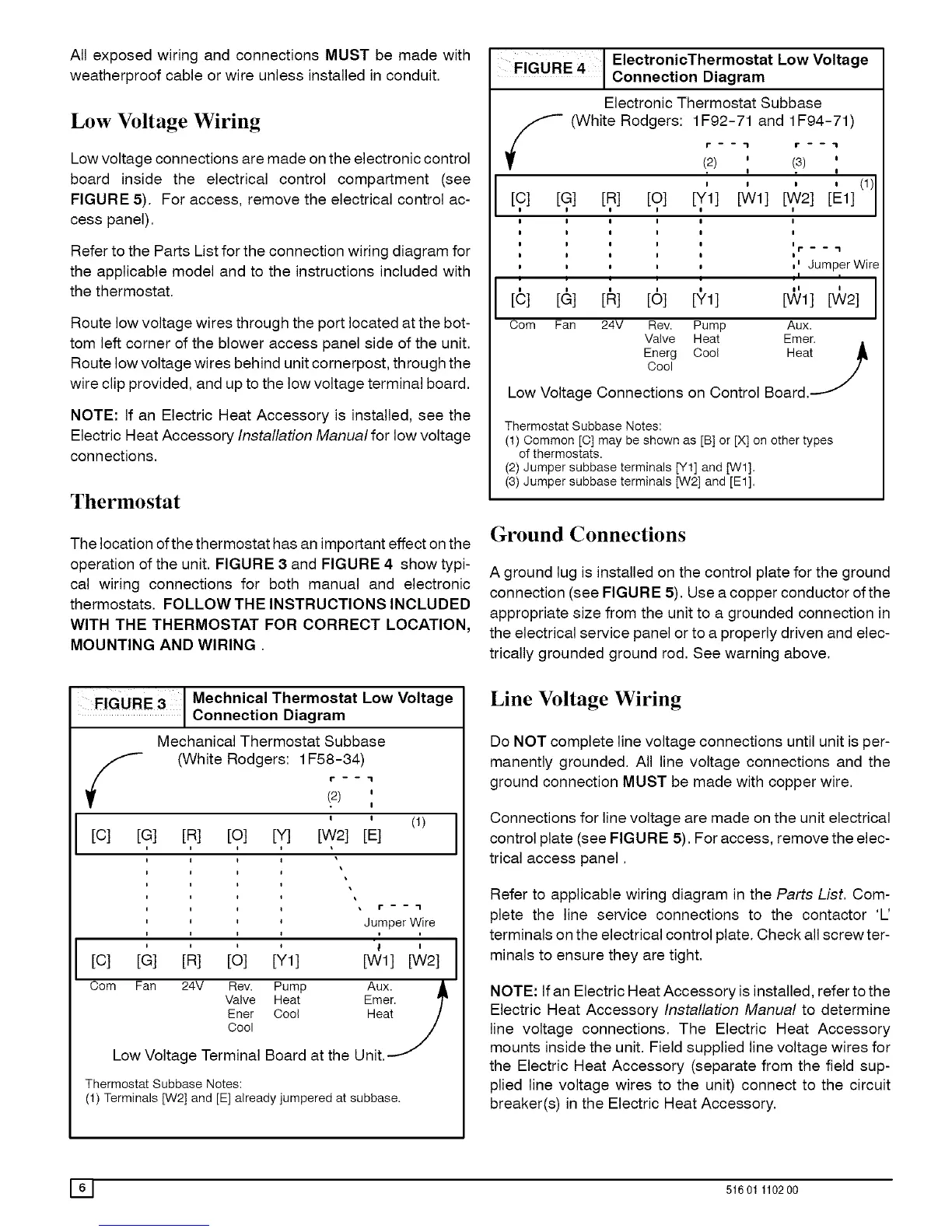
FIGURE 4 l ConnectionElectr°nicTherm°statDiagramLow Voltage
Electronic Thermostat Subbase
_ (White Rodgers: 1F92-71 and 1F94-71)
P - - "1 f - -- "1
(2) ' (3) '
I !
|
, , , , (1)l
[C] [G] [R] [O1 [YI] [Wl] [,W21 [Ell
I
! I
! !
I If. _ _ .I
I I
, ,' Jumper Wire
[C] [&] [1_] [61 [_'11 [V_I] [V_/21
Com Fan 24V Rev. Pump Aux.
Valve Heat Emer.
Energ Cool Heat
Cool
Low Voltage Connections on Control Board,
Thermostat Subbase Notes:
(1) Oommon [C] may be shown as [B] or [X] on other types
of thermostats.
(2) Jumper subbase terminals [Y1] and [W1].
(3) Jumper subbase terminals [W2] and [El].
Ground Connections
A ground lug is installed on the control plate for the ground
connection (see FIGURE 5). Use a copper conductor of the
appropriate size from the unit to a grounded connection in
the electrical service panel or to a properly driven and elec-
trically grounded ground rod, See warning above.
Line Voltage Wiring
Do NOT complete line voltage connections until unit is per-
manently grounded. All line voltage connections and the
ground connection MUST be made with copper wire.
Connections for line voltage are made on the unit electrical
control plate (see FIGURE 5), For access, remove the elec-
trical access panel.
Refer to applicable wiring diagram in the Parts List. Com-
plete the line service connections to the contactor 'U
terminals on the electrical control plate. Check all screw ter-
minals to ensure they are tight.
NOTE: If an Electric Heat Accessory is installed, refer to the
Electric Heat Accessory Installation Manual to determine
line voltage connections. The Electric Heat Accessory
mounts inside the unit. Field supplied line voltage wires for
the Electric Heat Accessory (separate from the field sup-
plied line voltage wires to the unit) connect to the circuit
breaker(s) in the Electric Heat Accessory,
61 51601 110200