©2017 ICS - Blount Inc, Specications subject to change without notice. REV19JUNE2017 P/N 598901
39
695XL SERVICE MANUAL
13. IGNITION MODULE
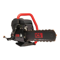
13.1
• Remove starter cover.
• Remove starter cover shield.
• Disconnect the stop switch cable.
• Inspect and replace if damaged
(P/N 544032).
13. This section covers the removal, inspection and installation of the ignition
module. Removal of the starter is required. Refer to section 8 if necessary.
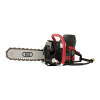
13.2
• Remove (2) ignition module screws
(P/N 544038).
• Remove ignition module (P/N 544036).
• Inspect and replace if damaged.
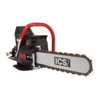
13.3
Reassemble in reverse order.
Place air gap gauge (.010 in/0.3 mm) on
the magnet side of the ywheel.
• Set ignition module in place.
• Install ignition module screws with blue
Loctite
®
242.
• Holding gauge, rotate ywheel
magnets around to coil.
• Torque ignition coil screws to 89-105
in/lbs (10 - 12 Nm).
• Remove gauge, rotate ywheel and
check for clearance.
• Connect stop switch cable.
12. This section covers the removal, inspection and installation of the guide bar stud.
Removal of WallWalker
®
and muer is required. Refer to section 10 if necessary.

 Loading...