16
Installation and Servicing
SECTION 2 - INSTALLATION
2.3 MOUNTING THE HEAT INTERFACE UNIT
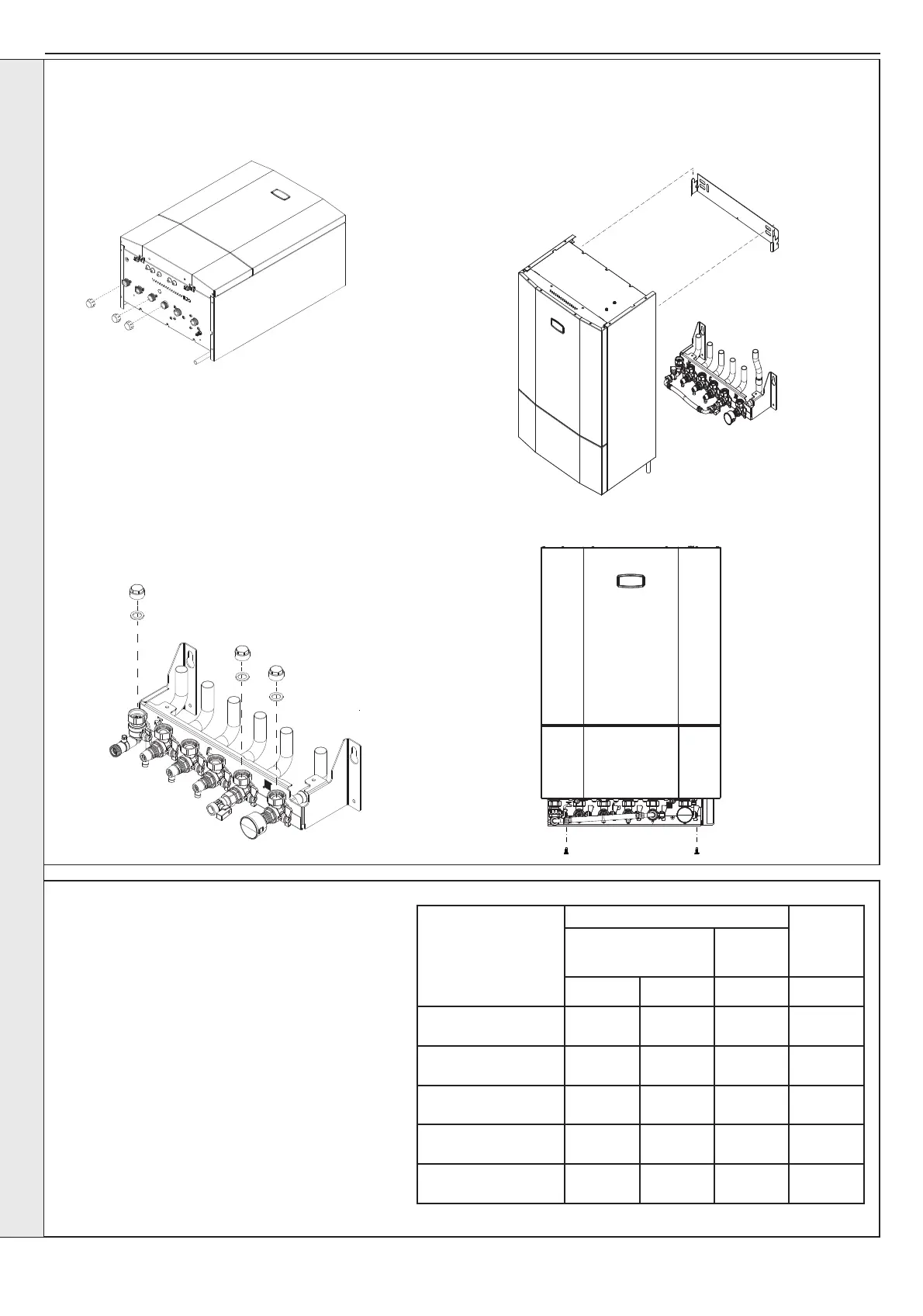
Flow Regulator
Flow Rate / Colour
Housing / Colour
Core
Flow Tolerance
Power
Rating
Deviations
Pressure
Range
+10% -10% (bar) kW
12.3 l/min / natural /
orange
10 10 1 - 10 30
16.4 l/min / natural /
green
10 10 1 - 10 40
20.5 l/min / natural /
yellow
10 10 1 - 10 50
27.0 l/min / natural /
natural
10 10 1.5 - 10 60
28.7 l/min / natural /
dark grey
10 10 1.5 - 10 70
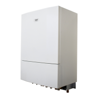
1. Ensure the plastic plugs are removed from both the
Primary and DHW connections before mounting the HIU.
Note: HIU may contain residual water.
2. Indirect only
a. Isolate the incoming cold water mains prior to the HIU.
b. Ensure isolation valves are in the closed position (handles
horizontal).
c. Remove brass plugs from the top of the isolation valves (if
used). Discard any used gaskets.
4. Lift the HIU onto the wall mounting plate (refer to the
Introduction section for safe handling advice), locating it
over the two tabs. The HIU unit will need to be lifted clear
of lower bracket connections to sit ush.
5. Install 2 x HIU securing screws from underneath of
bracket.
2.4 CONNECTIONS
Continued....
With the appliance in place, insert a G3/4 bre
gasket between the top of each isolation valve
and the appliance connection. Tighten each nut to
16.6Nm.
NOTES.
Ensure all connection blanking plugs are removed
before connecting hardware. Each valve must be
tted to the correct connection as shown in the
picture.
Ensure each union is tted with bre seals provided.
Do not subject any of the isolating valves to heat
other than normal operation as the seals may be
damaged.
INSTALLATION