42
Installation and Servicing
SECTION 3 - SERVICING
3.20 PCB REMOVAL & REPLACEMENT
Note: Fit the earth strap to your wrist and secure to a suitable earth on the HIU chassis.
1. Ensure the HIU is disconnected from the Mains power supply and if the credit control valve is tted ensure this is also powered
down to prevent exposure to mains electricity.
2. Refer to Section 3.4 to remove front panel.
3. Gently fold down the plastic front panel to expose the back of the control box enclosure.
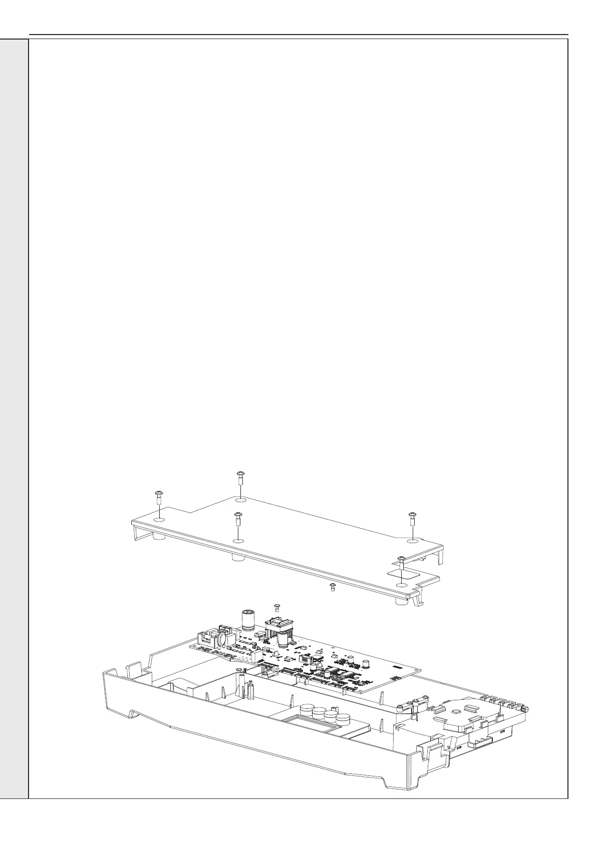
4. Remove the 5 screws and lift the back plastic panel away.
5. Unplug all connections to PCB.
6. Remove two screws which retain PCB in position.
7. Lift the PCB out of the plastic enclosure.
8. Ensure all control board selection buttons are correctly located in the front panel before retting the new PCB.
9. Place new PCB inside plastic enclosure and reassemble in reverse order.
10. Once the HIU front panel is secured switch the mains power on to begin setting up the new PCB parameters.
11. a. On power up the new PCB will show ‘uP’.
b. Press RESET, display now shows ‘oF’.
c. Power down the HIU at the mains, wait for 10 seconds and power on again.
d. Display shows ‘F9’.
e. Press the ‘+’ or ‘-’ button to progress to the HIU type setting screen.
f. Using the ‘+’ or ‘-’ button the display will be able to by cycled between II (Indirect CH & Indirect DHW), dI (Direct CH &
Indirect DHW) and It (Indirect CH & tanked storage DHW). Once the correct HIU type has been chosen, press the enter
button to progress to the DHW plate sizing screen.
g. Using the ‘+’ or ‘-’ button the display will be able to be cycled between 30, 40, 50, 60 or 70 depending on the HIU selected.
Once the correct DHW capacity has been chosen press enter to progress to the CH maximum ow temperature setting
screen. This feature allows the installer to limit the ow temperature to protect underoor heating systems and vulnerable
users.
h. Use the ‘+’ or ‘-’ buttons to increment/decrement the maximum CH ow temperature in 1° C increments between 30-80° C.
j. Once correct maximum temperature has been selected press enter to complete the set up.
k. Power down the HIU at the mains, wait for 10 seconds and power up again. This will ensure the valves are calibrated
correctly for the HIU type.
The HIU is now ready for normal operation.
IMPORTANT. IT IS CRITICAL FOR
SAFE OPERATION THAT THE
CORRECT HIU SIZE AND TYPE IS
ENTERED INTO THE HIU.
SERVICING