43
Installation and Servicing
SECTION 3 - SERVICING
7
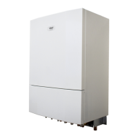
3.21 DHW FLOW REGULATOR
1. Isolate and drain down the HIU. Refer to Section 3.5.
2. Remove the front panel. Refer to Section 3.4.
3. Remove insulation front section. Refer to Section 3.12.
4. Disconnect the connector on the ow turbine harness.
5. Slacken and disconnect isolation valve nut on the mains
DCW feed into the HIU appliance on the rst x bracket.
6. Remove and retain the two screws securing the manifold
to the bottom panel.
7. Slacken and disconnect pipe nut into the DHW plate from
the cold feed (top left of plate heat exchanger).
8. Lift up and rotate cold water feed pipe leg with manifold
attached out from the HIU.
9. Using a pair of pliers, pull out/remove plastic ow
regulator.
10. Clean the inlet mesh lter, check the O-ring seal and ret
with the lter mesh facing outward. If replacing the ow
restrictor cartridge, ensure that it is correctly sized for the
unit it is been tted to and cartridge colour coding is the
same.
11. Re-assemble in reverse order, replacing all gaskets where
appropriate.
12. Rell the HIU. Refer to Section 2.5.
13. Check that the HIU operates in both DHW & CH modes.
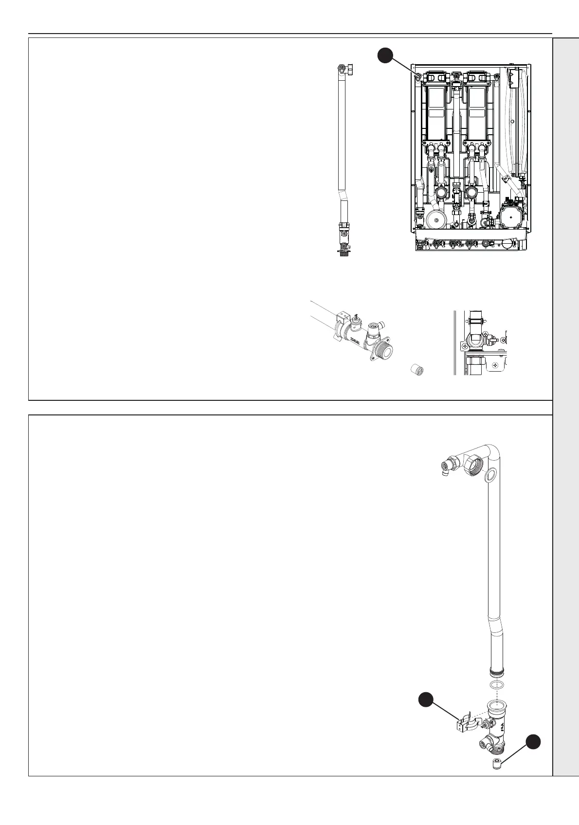
3.22 DHW FLOW MANIFOLD WITH INTEGRATED TURBINE ASSEMBLY REPLACEMENT
1. Isolate and drain down the HIU. Refer to Section 3.5.
2. Remove the front panel. Refer to Section 3.4.
3. Remove insulation front section. Refer to Section 3.12.
4. Disconnect the connector on the ow turbine harness.
5. Slacken and disconnect isolation valve nut on the mains DCW feed into the HIU appliance
on the rst x bracket.
6. Remove and retain the two screws securing the manifold to the bottom panel.
7. Slacken and disconnect pipe nut into the DHW plate from the cold feed (top left of plate heat
exchanger).
8. Lift up and rotate cold water feed pipe leg with manifold attached out from the HIU.
9. Using a suitable tool retract the metal pipe clip and remove the pipe from the manifold.
10. Using a pair of pliers pull out / remove the plastic ow regulator from the base of the
manifold inlet. Make sure the complete cartridge has been removed from the inlet of the
manifold.
11. Clean the inlet mesh lter, check the O-ring seal and ret with the lter mesh facing outward.
If replacing the ow restrictor cartridge, ensure that it is correctly sized for the unit it is been
tted to and cartridge colour coding is the same.
12. Replace the O-ring on the cold water feed pipe and insert into new DHW ow turbine
housing manifold.
13. Re-assemble metal pipe clip.
14. Re-assemble in reverse order, replacing all gaskets where appropriate.
15. Rell the HIU. Refer to Section 2.5.
16. Check that the HIU operates in both DHW and CH modes.
9
10
SERVICING