5.6 Mounting valve-box into a panel
Recommended panel thickness should be in the range 14.5 to 26mm. Cut large hole in the panel (see 5.4)
at the desired location for the valve-box. Decide on preferred mounting option (see 4.3). Two mounting
methods are discussed below.
Note: before mounting, it may be easier to t pipe connectors to valve-box (see 5.1).
DIRECT MOUNTING OPTION (A) can be used with long wood
screws and suitable washers. Guide the valve-box into the large
hole, until it stops against the rear of the panel. Check level &
valve-box orientation (see 4.5). Conrm valve-box is projecting
from the front of the panel between the min
& max depth markers (see 4.2). Pack-out if necessary.
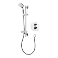
Fit a screw into each corner slot of the valve-box from
the rear to secure to panel. Care should be taken to
prevent screws drifting towards the large hole.
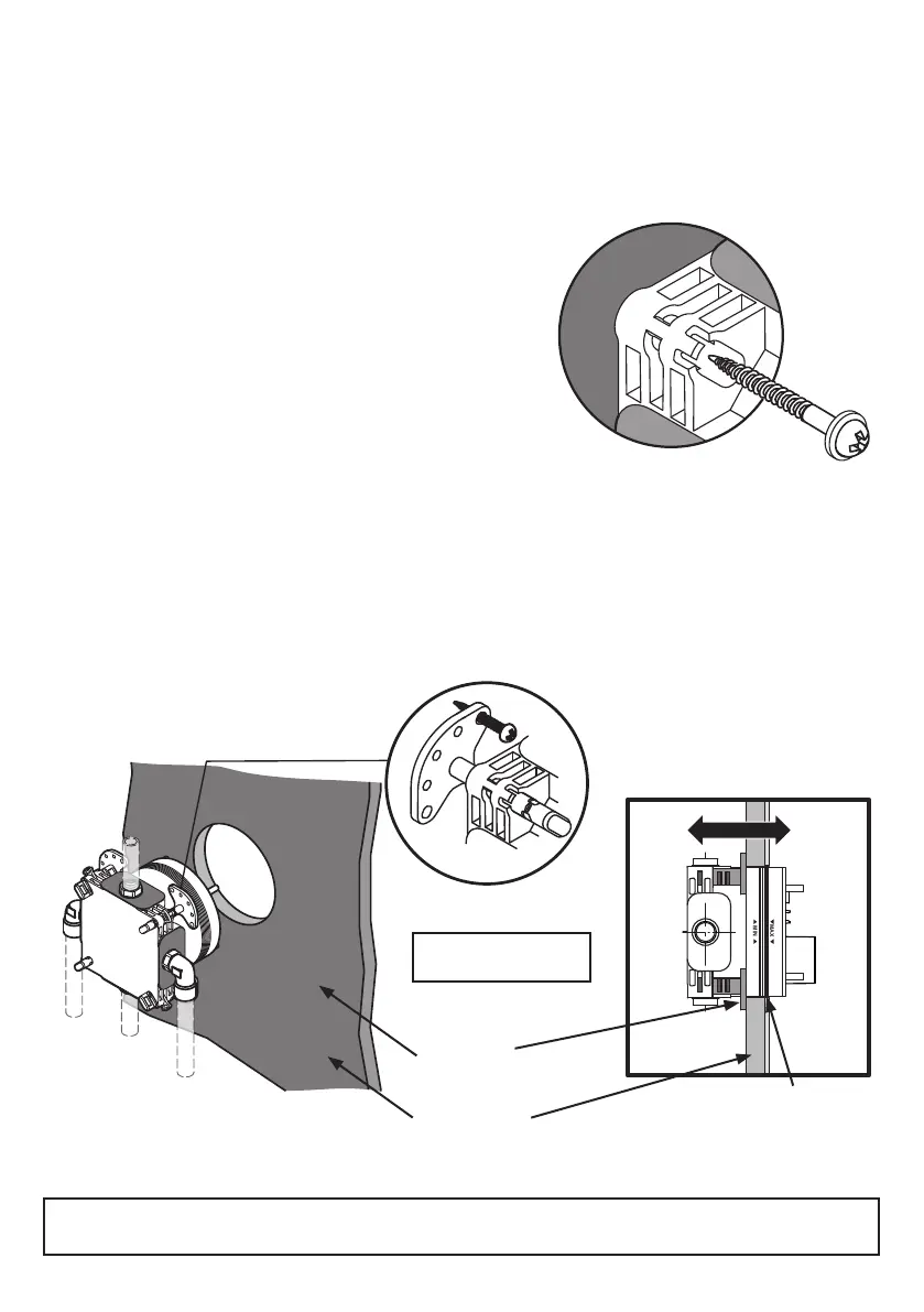
ADJUSTABLE LEGS OPTION (C) t the OPTIONAL legs to the valve-box, from the front; to the desired
depth (see 4.3C & 5.3). Guide the valve-box into the large hole, until the legs stop against the rear of the
panel. Check level & valve-box orientation (see 4.5). Conrm valve-box is projecting from the front of the
panel between the min & max depth markers (see 4.2). Adjust leg positions if necessary.
Mount the valve-box to the panel using wood screws though the leg xing holes
MIN
MAX
IMPORTANT: Ensure the panel is capable of supporting the valve-box securely with the screws being used.
Check that the screw length will not penetrate through the front of the panel & spoil the visible surface.
Mounting option C illustrated above using OPTIONAL adjustable xing legs.
Observe
depth
Plasterboard
Adjustable
legs
20
For adjustable leg
details, see 5.3
 Loading...