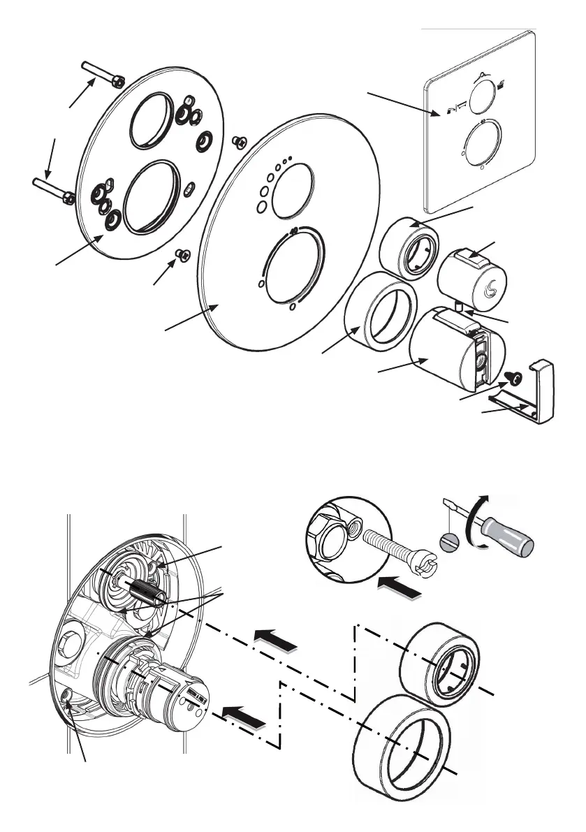
6.1 Description of chrome trim (kit-2)
6.2 Installation of chrome trim (kit-2)
Ensure preparation work has been completed (see 6.0). The two up-stand bolts can be screwed into the
valve body using a slotted screw driver at the positions shown. Do not screw these bolts right down, as they
may require adjustment to accept the screws in the next step (for xing the lid).
Location for tting
1st up-stand bolt
Shroud locating
diameters (o-rings)
Location for fitting
2nd up-stand bolt
Up-stand
bolts
Valve-box lid
with integral
seals
Lid fixing
screws
Escutcheon plate:
on/off flow control
version
Flow control
shroud (small)
Temperature shroud (large)
Temperature handle
Temperature handle cover
Flow
control
handle
screw
An alternative
escutcheon plate:
diverter version
Flow control
handle
30
Temperature handle screw
 Loading...