12
4.6 Kit-1 description
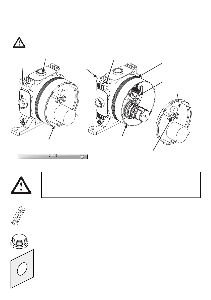
The built-in valve-box is supplied with a plaster guard (protective cover) tted as shown. The plaster guard
prevents debris entering into the valve-box during installation. Additionally, the plaster guard also serves as
an aid to levelling the valve-box whilst mounting onto a wall or panel.
OBSERVE ORIENTATION OF VALVE-BOX, SEE 4.5.
2x inlets
at sides
2x outlets at
top&bottom
Sealed valve-box
4 mounting slots in
corners of valve-box
Trimming
guide lines
Valve assembly
inside
Plaster guard
Plaster guard
locating lugs
This clip can be used to hold a miniature
spirit level (not supplied)
4 bosses can be used as a platform
for a spirit level during installation
IMPORTANT: The valve-box is tted with seals to prevent any water from leaking into the
wall cavity. Therefore the inside of the valve-box should not be drilled otherwise water
tightness will be lost. See 4.7.
ALWAYS UTILISE THE 4 SLOTS PROVIDED IN THE CORNERS
OF THE VALVE-BOX FOR MOUNTING THESE PRODUCTS.
Latching clips: (pair supplied) are used to attach and secure the mounting bracket (&
adjustable legs) to the valve-box by using a pair of corner slots. A mounting bracket is also
supplied, see 4.3B.
Blanking plug: (threaded G1/2”) to permit one mixed water outlet (either top or bottom) to
be blanked-off (if it is not required). Use a 10mm Allen Key to drive plug. Plug is not sup-
plied with diverter version of products.
Fleece mat: (tiling aid) is supplied to help protect the wall cavity from water splashes
which might penetrate from any gaps in the tiles around the valve-box. The mat should be
placed over the valve-box and bonded to the wall using tile adhesive immediately prior to
tiling (see 4.7).
The eece mat is soft & exible (water resistant) & will stretch around the valve-box diam-
eter. For panel installations, the mat can be discarded & a suitable sealant should be used
around the panel hole.
 Loading...