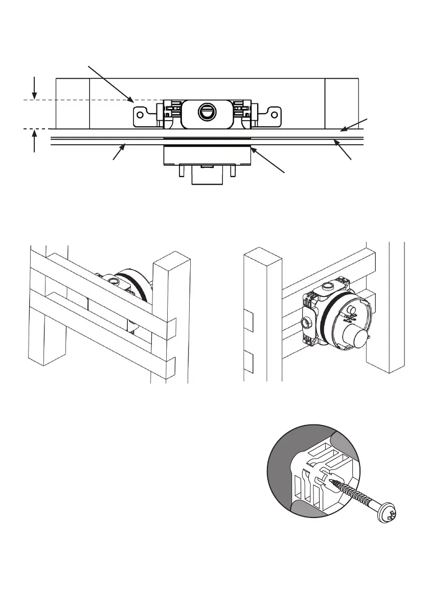
5.7 Mounting valve-box into a timber stud wall, cont
Illustrated above, valve-box being mounted onto a pair of slim noggins (30mm*) attached to the back of a
pair of studs. Framework shown here uses 75x50 timbers on 400 centres. (Wall cavity = 75mm).
DIRECT MOUNTING OPTION (A) can be used with long
wood screws and suitable washers. Position the valve-box
onto the noggins. Check level & valve-box orientation (see
4.5). Conrm valve-box will project from the front plaster
board between the min & max depth markers (see 4.2).
Pack-out if necessary.
Fit a screw into each corner slot of the valve-box from
the front to secure to the framework.
DEEP CAVITY WALLS
In some cases the partition wall may use timbers which are 100x50 or greater.
*Noggin thickness should be adjusted accordingly.
Greater wall cavity will also permit mounting by using adjustable legs kit. In principle, the method is same
as shown in 5.5 (for solid wall). In this case the legs could be secured to a pair of noggins as shown above.
(Typical dimensions are given here, for guidance only).
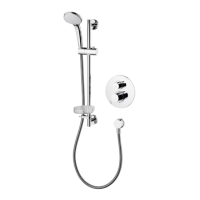
Mounting
bracket
Stud
Stud
45 min
cavity
Tiles 8-10
Observe
depth
Adhesive 2-3
Plasterboard
12,5
Plan view showing valve-box installed into partition wall, using mounting bracket.
Direct mounting
Alternatively, the valve-box can be mounted directly using the corner slots.
22
 Loading...