44
EVOMAX - Installation & Servicing
SERVICING
SERVICING
8
4
3
58
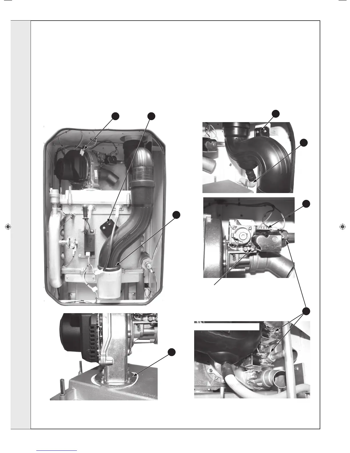
REMOVAL OF FAN AND GAS VALVE ASSEMBLY
1. Refer to Frame 55.
2. Remove the upper front panel, Refer to Frame 57.
3. Remove the two screws retaining the ue tube to the
heat exchanger.
4. Lift the lower section of ue upwards to disengage
from the sump then twist outwards and pull down to
completely remove..
5. Disconnect condensate pipe from upper ue elbow.
6. Remove the ue tube elbow xing screws and remove
elbow by pulling downwards.
7. Disconnect the electrical connections from the gas valve/s.
8. Disconnect the electrical connections from the fan.
9. Undo the gas valve union nut/nuts and retain the bre
washer/s.
10. Remove the four nuts/washers (or screws depending upon
boiler size) retaining the fan assembly and remove the fan
assembly.
11. Inspect & clean as necessary.
12. Re-assemble in reverse order replacing all gaskets.
6
5
7
9
150 Model with Dual Gas Valves
Inlet Gas Pressure Test Point for 30, 40, 60 80 & 150 models
For 100 & 120 models the inlet gas pressure test point can be
found on the inlet gas manifold
10
206210-3.indd 44 09/06/2011 13:34:42
 Loading...