16
EVOMAX - Installation & Servicing
INSTALLATION
18
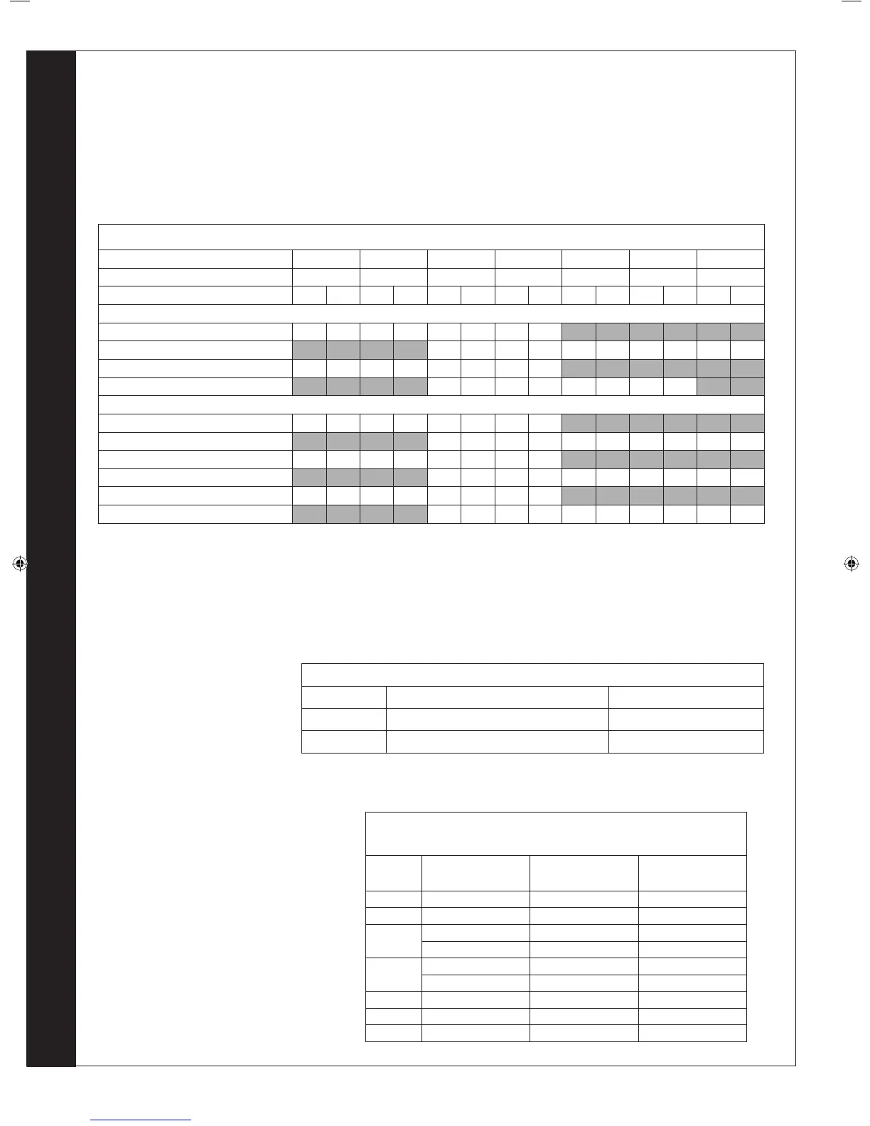
FLUE RESISTANCES
CONCENTRIC FLUE SYSTEMS
For concentric ue systems with elbows tted, use the table to correct the maximum ue extension capability. Alternatively use the
table to design the ue system, deducting the individual resistance of components from the maximum pressure drop allowed in the
ue for that boiler.
The maximum pressure drop allowed in the ue is given below.
Note: The resistances are given in Pa and also the equivalent length of straight concentric pipe.
FLUE OUTLET
Model 100 120 150
3
47.6 63.4 95.1 128.3 160.3 192.5 240.7
Pa m Pa m Pa m Pa m Pa m Pa m Pa m
Terminals
Vertical roof kit 80 / 125 21 6 45 7 86 6.2 135 4.8
Vertical roof kit 100 /150 30 7.6 70 8 65 3.5 100 3.3 172 4.3
Horizontal wall kit 80 / 125 + 90° 21 6 45 7 86 6.2 135 4.8
Horizontal wall kit 100 / 150 + 90° 30 7.6 70 8 65 3.5 100 3.3
Pipes & Elbows
45° bend 80 / 125 3.5 1.1 7.5 1.1 13.5 1.1 22 1.1
45° bend 100 / 150 8 1.2 15 1.2 24 1.2 35 1.2 50 1.2
90° bend 80 / 125 7.0 1.6 14.0 1.6 25 1.6 40 1.6
90° bend 100 / 150 13 2 23 2 37 2 50 2 75 2
Straight 1m length 80 /125 3.3 1 4.8 1 15.6 1 21.7 1
Straight 1m length 100 /150 4.4 1 7.1 1 11 1 16.4 1 38.7 1
Models 30/30P, 40/40P, 60/60P, 80/80P
Models 100 / 120 / 150
90° Elbow 2.1 2.7
45° Elbow 0.6 1.8
Concentric ues including terminal
Model Flue Size Pressure diff (Pa)
Length
(m)
30/30P 80 / 125 140 42
40/40P 80 / 125 200 42
60/60P
80 / 125 117 7.5
100 / 150 133 30
80/80P
80 / 125 260 12
100 /150 250 35
100 100 / 150 220 20
120 100 / 150 288 17.6
150 100 / 150 291 7.5
For open ue systems with
elbows tted, use this table to
correct the maximum extension
capability. The table shows the
equivalent length of ue tube for
the elbow required.
206210-3.indd 16 09/06/2011 13:34:19

 Loading...


