45
CHAPTER 8
CHAPTER 8 - WIRING
8.1. Internal Wiring
ELECTRICAL SHOCK HAZARD. For your safety,
disconnect electrical power supply to the
unit before servicing or making any electrical
connections to avoid possible electric shock
hazard. Failure to do so can cause serious
injury, or death.
Prior to servicing, label all wires before discon-
necting. Wiring errors can cause improper and
dangerous operation. Verify proper wiring and
operation after servicing.
8.1.1 General Requirements
• Wiring must be N.E.C Class 1.
• If original wiring as supplied with the unit must
be replaced, use only Type T 194ºF [90ºC] wire or
equivalent as a minimum.
• The EXALT Solo must be electrically grounded as
required by National Electrical Code (ANSI/NFPA
70) for installations in the U.S., or the Canadian
Electrical Code Part 1(CSA C22.1) for installations in
Canada.
WARNING
CAUTION
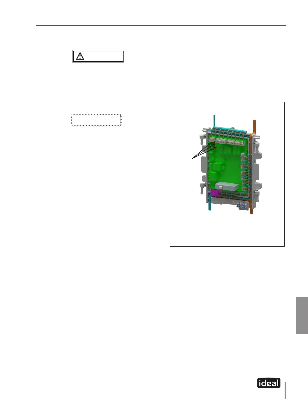
8.1.2 Fuse Locations
• The CTRLMax control module contains 3 internal
replaceable 5A fuses as shown in Fig. 29 below.
• The top two fuses protect the EXALT as well as the
CH, DHW, and Flame outputs.
• A 2.5A fuse is also located on the terminal strip, to
protect the output. Refer to Fig. 32 on page 48.
Fig. 29 - CTRLMax Control Module Fuse Location
Location of fuses
 Loading...