42
xtra
- Installation & Servicing
FAULT FINDING
FAULT FINDING FAULT FINDING FAULT FINDING FAULT FINDING FAULT FINDING FAULT FINDING
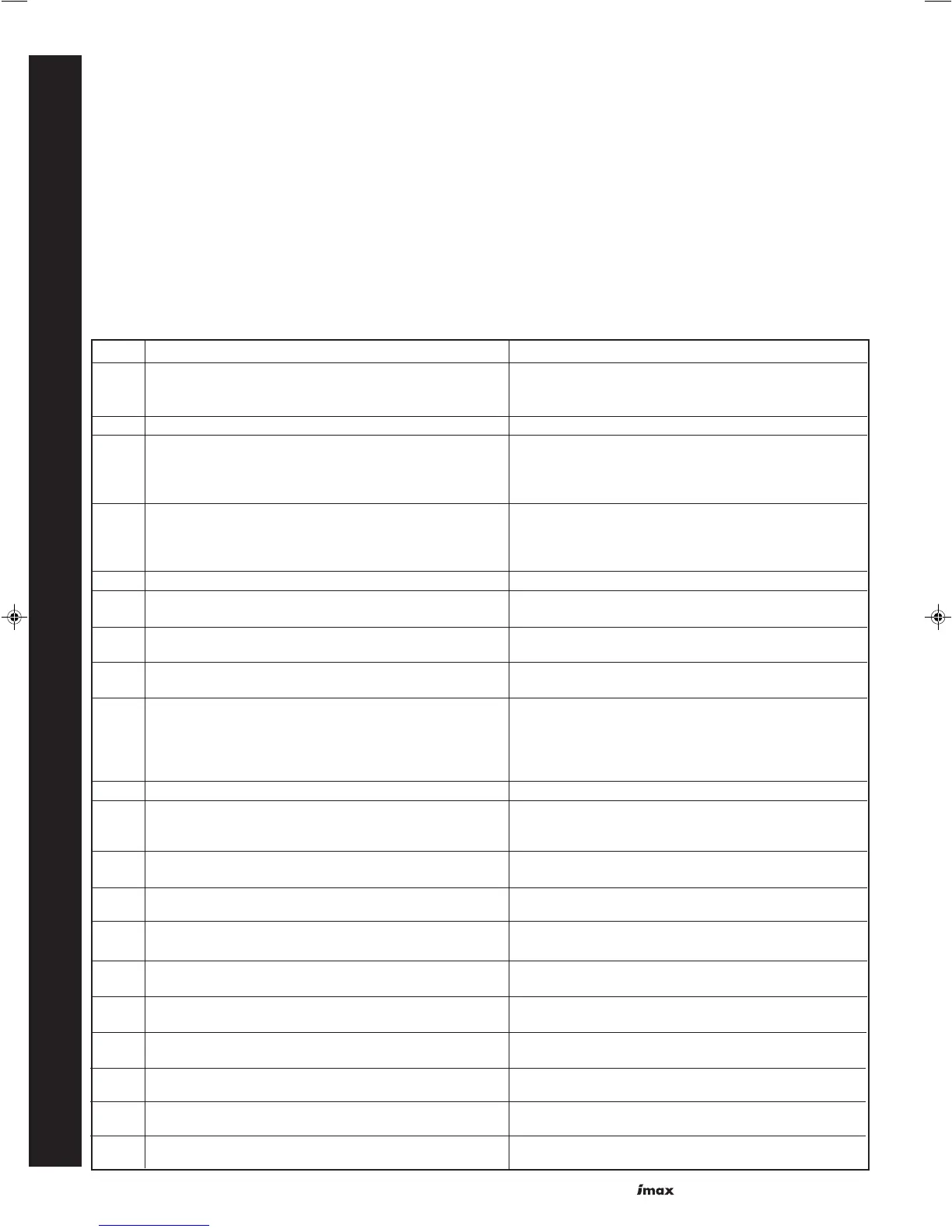
Code Description Action
FUSE 24V circuit dead Check Transformer & replace if necessary
Check 24V fuse on Control Board
If 24V fuse blown check for short circuits before replacing
00 Flame Error (signal present when there should not be) Replace Control Module
02 No ignition after restart Check inlet gas pressure
Check wiring to ignition/detection electrode
Check condition of ignition/detection electrode
If above OK replace control module
03 Internal Failure Check gas valve wiring
Check gas valve solenoids not open circuit
Check general wiring harness and connections
If all OK. replace control module
04 Non-volatile lockout Press reset
05 Internal failure Check wiring harness & connections
If wiring OK replace control module
06 Internal failure Check wiring harness & connections
If wiring OK replace control module
07 Internal failure Check wiring harness & connections
If wiring OK replace control module
08 Air Pressure Switch did not close Check flue for blockage
Check/clean burner
Check Air Pressure Switch sensing pipes condition
Check fan speed
Check air Pressure Switch & replace if necessary
11 EPROM read/write error Press reset. If fault keeps re-occuring Replace Control Module.
12 24V fuse blown Check 24V fuse on Control Board
If 24V fuse blown check for short circuits before replacing
Check gas valve leads & solenoids for short circuit
13 Internal failure Check wiring harness & connections
If wiring OK replace control module
14 Internal failure Check wiring harness & connections
If wiring OK replace control module
15 Internal failure Check wiring harness & connections
If wiring OK replace control module
16 Internal failure Check wiring harness & connections
If wiring OK replace control module
17 Internal failure Check wiring harness & connections
If wiring OK replace control module
18 Flow temperature too high Check no air in system or boiler
Check adequate flow of water through boiler
19 Return temperature too high Check no air in system or boiler
Check adequate flow of water through boiler
25 Flow temperature rise too fast Check no air in system or boiler
Check adequate flow of water through boiler
28 No tacho signal from fan Check wiring to fan
If wiring OK replace fan
Before attempting any electrical fault finding ALWAYS carry out
the preliminary electrical system checks as detailed in the
Instructions for the British Gas Multimeter or other similar
commercially available meter.
The preliminary electrical system checks are the FIRST
electrical checks to be carried out during a fault finding
procedure.
On completion of any service/fault finding task which has
required the breaking and remaking of electrical connections
the following checks MUST be repeated:
a Earth continuity
b Polarity
c Resistance to earth
Detailed instructions on the replacement of faulty components
are contained in the 'Servicing' section of these Installation &
Servicing Instructions.
Before carrying out Fault Finding ensure that all external controls
are calling for heat. There should be 230V ± 10% available at the
control box connection.
The boiler control module has replaceable fuses protecting the
230V and 24V circuits. A common reason for the 230V fuse to
blow would be if the pump connected to the boiler was drawing
more than 1 amp.
If the 230V fuse has blown, the display will be blank. Check for
short circuits and pump loads before replacing the fuse.
Boiler Control Module Error Codes