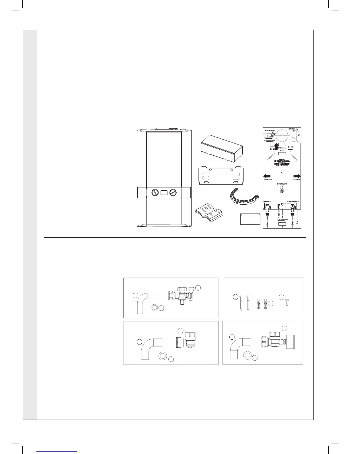
EasyManuals Logo

IDEAL Logic SYSTEM 15 User Manual

IDEAL Logic SYSTEM 15
68 pages
To Next Page IconTo Next Page
To Previous Page IconTo Previous Page
Page #14 background imageLoading...
Page #14 background image
14
INSTALLATION
Ideal Logic System - Installation and Servicing
6
UNPACKING
The boiler is supplied fully assembled in Pack A. A telescopic or non-telescopic ue assembly for rear or side ue outlet in Pack
B is suppled as a separate order.
Unpack and check the contents.
Pack A Contents
A Boiler
B Hardware Pack Box
C Wall Mounting Plate
D These Installation/Users Instructions
E Wall Mounting Template
(located on internal protective
packaging)
F Turret Clamp
G Boiler Guarantee & Registration Pack
C
A
D
F
B
E
205552-10138b
G
Boiler Guarantee
HARDWARE PACK CONTENTS
Gas Valve Pack
1. Pipe - Gas Inlet
2. Washer - Gas (blue)
3. Gas Cock
Return Valve Pack
1. Pipe CH Return
2. Washer CH
3. Valve Return
Accessory Pack
1. Screw (x2)
2. Wallplug (x2)
3. Turret Clamp Screw (x1)
Flow Valve Pack
1. Pipe CH Flow
2. Washer CH
3. Valve Flow (with gauge)
Gas Valve Pack
Accessory Pack
Flow Valve Pack
Return Valve Pack
1
1
1
1
2
3
3
2
2
2
3
3
INSTALLATION

Questions and Answers:

Question and Answer IconNeed help?

Do you have a question about the IDEAL Logic SYSTEM 15 and is the answer not in the manual?

IDEAL Logic SYSTEM 15 Specifications

General IconGeneral
ModelLogic SYSTEM 15
CategoryBoiler
Output15 kW
Efficiency93%
Dimensions700 x 395 x 278 mm
Fuel TypeNatural Gas
ErP RatingA
TypeSystem Boiler
MountingWall Mounted
Water Pressure3 bar

Related product manuals