Model 15 18 24 30
Max CH uutput kW 15 18 24.2 30.3
(Btu/h) (51,300) (61,600) (82,600) (103,300)
Water ow rate l/min 10.7 13 17.2 21.5
(gal/min) (2.4) (2.8) (3.8) (4.7)
Temp differential
o
C 20 20 20 20
(
o
F) (36) (36) (36 (36)
Head available m.w.g. 5 4.5 3.3 1.9
for system (ft.w.g.) (16.2) (14.7) (10.8) (6.2)
General
1. The installation must comply with all relevant national and local
regulations.
2. The installation should be designed to work with flow
temperatures of up to 86
o
C.
3. All components of the system must be suitable for a working
pressure of 3 bar and temperature of 110
o
C. Extra care should
be taken in making all connections so that the risk of leakage is
minimised.
The following components are incorporated within the appliance:
a. Circulating pump.
b. Safety valve, with a non-adjustable preset lift pressure of 3
bar.
c. Pressure gauge, covering a range of 0 to 4 bar.
An 8-litre expansion vessel, with an initial charge pressure
of 0.75 bar.
4. Provision must be made for replacing water
loss from the system, either :
a. From a manually lled ‘make-up’ vessel with a readily visible
water level. The vessel should be mounted at least 150mm
above the highest point of the system and be connected
through a non-return valve to the system, tted at least
150mm below the ‘make-up’ vessel on the return side of
the radiators. or
b. Where access to a ‘make-up’ vessel would be difcult, by
pre-pressurisation of the system.
The maximum cold water capacity of the system should
not exceed 143 litres. This is the maximum system
volume for the boiler expansion vessel. If the capacity of
the vessel is not considered sufcient for this, or for any
other reason, an additional vessel MUST be installed on
the return to the boiler.
Guidance on vessel sizing is given in table opposite.
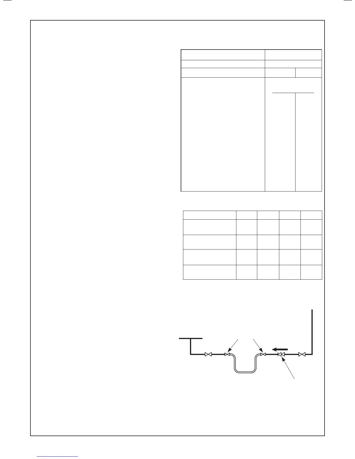
5. Filling
The system may be lled by the following method:
Through a temporary hose connection from a ‘draw-off’ tap,
supplied from a service pipe under mains pressure. Where the
mains pressure is excessive, a pressure reducing valve must be
used to facilitate lling. When installing the lling device, it must
be connected as below to fully comply with the water regulations.
This may involve the tting of an additional WRAS approved
isolator valve to the mains supply.
i. Thoroughly ush out the whole system with cold water.
ii. Fill and vent the system until the pressure gauge registers 1.5
bar, and examine for leaks.
iii. Check the operation of the safety valve by raising the water
pressure until the valve lifts. This should occur within 0.3 bar
of the preset lift pressure.
iv. Release water from the system until the minimum system
design pressure is reached; 1.0 bar if the system is to be pre-
pressurised.
Notes
a. The method of lling, relling, topping up or ushing sealed primary
hot water circuits from the mains via a temporary hose connection
is only allowed if acceptable to the local water authority.
b. Antifreeze uid, corrosion and scale inhibitor uids suitable for use
with boilers having aluminium heat exchangers may be used in the
central heating system.
2
SYSTEM REQUIREMENTS - Central Heating
bar 3.0
bar 0.5 to 0.75
bar None 1.0
25 1.6 1.8
50 3.1 3.7
75 4.7 5.5
100 6.3 7.4
125 7.8 9.2
150 9.4 11.0
175 10.9 12.9
190 11.9 14.0
200 12.5 14.7
250 15.6 18.4
300 18.8 22.1
0.063 0.074