67
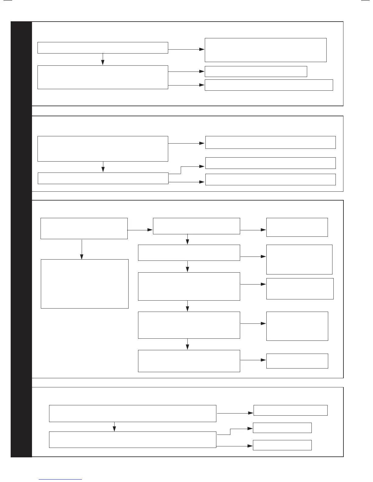
Restart the boiler, does Boiler Work OK?
NO
Check routing and integrity of internal boiler
wiring is OK. Check condition of Flame Sense
Electrode and replace if deteriorated.
Separate the ame detection electrode in-line
connector. Is there continuity between the terminals
pins connected to the electrode?
YES
Replace Flame Detection Electrode
Check routing and integrity of internal boiler wiring.
YES
NO
68
Is the Boiler and CH System lled with water and all
isolation and radiator valves open (check pressure
gauge is between 1 to 1.5 bar)?
NO
Fill and vent the system and open all isolation valves
69
Does the boiler ignite for a short
time and then extinguish?
YES
Is the Gas Pressure available at
the Boiler Inlet (18 mbar)?
Check the detection electrode and
associated harness for: continuity,
visual condition and position (Refer
to Frame 48). Check if condensate
pipe is blocked. Check if ue is
blocked.
Replace as necessary
NO
Check gas supply and
rectify fault
NO
YES
Is 215Vdc supply available at the Gas
Valve while the ame is on? (* See note)
YES
Check spark generator and associated
harness for: continuity and visual
condition. (Refer to Frame 49) Are these
functioning correctly?
YES
Check ignition electrode and associated
harness for: continuity, visual condition
and position. (Refer to Frame 47) Are
these functioning correctly?
YES
Check siphon and condensate drain pipe
work for blockage and rectify if necessary.
Boiler now working OK?
Check wiring from gas
valve to PCB for continuity.
If the wiring is OK then
replace the PCB
NO
Replace Spark Generator
and Harness as necessary.
NO
Replace Ignition
Electrode and
associated harness as
necessary
NO
Replace Gas Valve
NO
* Note: due to the wave form of
the rectied voltage, the reading
will vary depending on the type of
meter used to measure the value.
In general terms a reading greater
than 150V indicates that the correct
voltage is supplied to the gas valve.
70
Does the wiring from the Fan to the PCB have secure connections at
both ends and has not deteriorated? Does the wiring have continuity?
YES
Rectify Wiring & connections
Is there 230Vac at the Blue and Brown connections
to the 3 way connection on the Fan?
NO
Replace PCB
Replace Fan
NO
YES
YES
Are connections on water pressure sensor secure?
RESTART PROCEDURE - To restart boiler, turn mode knob to restart position and immediately turn knob back to required setting.
NO
YES
Re-t connections
Replace water pressure sensor