EasyManuals Logo

IDEAL Logic+ SYSTEM 15 User Manual

IDEAL Logic+ SYSTEM 15
72 pages
To Next Page IconTo Next Page
To Previous Page IconTo Previous Page
Page #36 background imageLoading...
Page #36 background image
36
SERVICING
Ideal Logic + System - Installation and Servicing
36


1. Loosen the two screws retaining the front panel.
2. Pull the two spring clips down to disengage and pull panel
forward and upward and remove.
view from top of boiler
view from bottom of boiler
1
2
3
REPLACEMENT
3. Hook the panel onto the top retaining clips.
4. Push the panel until the 2 bottom spring clips engage
ensuring the 4 control knobs line up with the holes in the
front panel.
5. Re-tighten the two retaining screws.
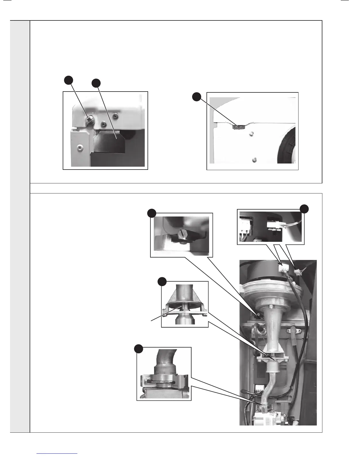
37

1. Disconnect the electrical leads from the fan.
2. Remove the clip from the gas control valve
outlet and ease the pipe upwards rotate and
then ease down to remove.
3. Remove the extended nut on the fan
mounting bracket.
4. Lift off fan and venturi assembly.
5. Undo the two M4 screws and release the
nozzle assembly.
6. Inspect the injector for blockage or damage.
7. Inspect fan outlet sealing gasket and replace
if necessary.
1
2
3
5
Injector


Questions and Answers:

Question and Answer IconNeed help?

Do you have a question about the IDEAL Logic+ SYSTEM 15 and is the answer not in the manual?

IDEAL Logic+ SYSTEM 15 Specifications

General IconGeneral
ModelLogic+ SYSTEM 15
CategoryBoiler
Output Rating15 kW
ErP RatingA
Fuel TypeNatural Gas
Dimensions (H x W x D)700 x 395 x 278 mm
TypeSystem Boiler
MountingWall Mounted
ERP Heating Efficiency93%
Standard Warranty7 Years

Related product manuals