20
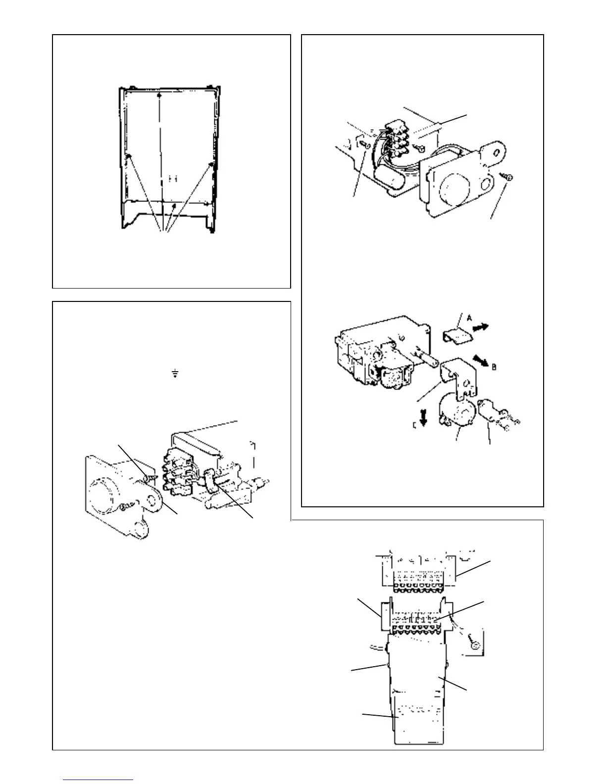
Back panel
mounting
bracket
Programmer
See note 5
Programmer
mounting
bracket
Stainless steel lid,
see note 5
Terminal strip,
see note 8.
See note 3
DETAIL OF PROGRAMMER
10. Fit the new programmer, terminal strip and wiring harness
in reverse order.
11. Set the programmer to the desired programme and test its
functions.
23 PROGRAMMER REPLACEMENT
(if fitted)
1. Refer to Frame 8.
2. Remove the boiler control box cover and release the
terminal strip fixing screw.
Disconnect the 'L', 'N' and
connections from the
terminal strip and release the cable clamp.
DETAIL OF BOILER CONTROL BOX
Terminal strip fixing
screw, see note 2.
Control box
cover
Cable clamp
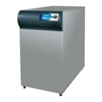
21 CASING SEAL REPLACEMENT
INNER VIEW OF BOILER CASING
1. Refer to Frame 8.
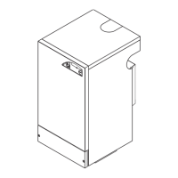
2. Remove the fixing screw retaining the control box cover
and remove the cover.
DETAIL OF CONTROL BOX
3. Unscrew the control box retaining screw and remove the
box from the gas control valve.
4. Pull off the electrical connections at the solenoid and
remove the earth wire connection at the solenoid bracket
5. Remove and replace the solenoid coil as shown below.
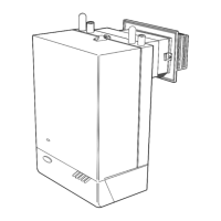
DETAIL OF GAS CONTROL VALVE
22 GAS VALVE SOLENOID REPLACEMENT
Control box
cover
Spring clip
8. Check the function of the gas control
valve
6. Re-assemble in
reverse order.
7. Replace the
boiler casing.
Refer to Frame 6.
3. Remove the 2 screws retaining the programmer mounting
bracket to the back panel mounting bracket.
4. Pull the programmer mounting bracket downward and
forward in order to disengage the terminal strip connection.
5. Remove the 2 screws fastening the stainless steel lid to
the programmer mounting bracket and remove the lid.
6. Slide the programmer upwards in order to clear the
mounting bracket.
7. Remove the strain relief bush retaining the control box
feed cable and remove the earth lead from the earth post.
8. Remove the 3 screws retaining the terminal strip to the
programmer mounting bracket.
9. Remove the programmer, complete with its terminal strip
and wiring harness.
1. Refer to Frame 8.
2. Remove the old seal from the casing surround.
3. Thoroughly clean the casing surfaces and fit the adhesive
seals.
4. Replace the boiler casing. Refer to Frame 6.
SERVICING
REPLACEMENT OF PARTS
Control box
retaining screw,
see note 3.
see note 2
Solenoid bracket
Solenoid
Control box
bracket
 Loading...