EasyManua.ls Logo

IDEAL RS30l RS40

IDEAL RS30l RS40
24 pages
To Next Page IconTo Next Page
Loading...
IDEAL CLASSIC
RS30, RS40, RS50 & RS60
CAUTION: To avoid the possibility of injury during the
installation, servicing or cleaning of this appliance, care should
be taken when handling edges of sheet steel components.
IMPORTANT: This appliance is for use with
NATURAL GAS ONLY.
NOTE TO THE INSTALLER: LEAVE THESE INSTRUCTIONS ADJACENT TO THE GAS METER
Installation & Servicing
Wall Mounted, Balanced Flue
Gas Boilers
Ideal Classic G.C. Appliance No.
RS 30 41 429 35
RS 40 41 429 36
RS 50 41 429 37
RS 60 41 429 38
Question and Answer IconNeed help?

Do you have a question about the IDEAL RS30l RS40 and is the answer not in the manual?

IDEAL RS30l RS40 Specifications

General IconGeneral
BrandIDEAL
ModelRS30l RS40
CategoryBoiler
LanguageEnglish

Summary

INTRODUCTION

GAS SUPPLY

Information regarding gas supply and consultation with the local gas region.

LOCATION OF BOILER

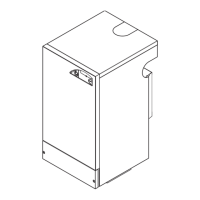
Requirements for installing the boiler's physical location and wall mounting.

FLUE INSTALLATION

FLUE TERMINAL POSITIONING

Specifies minimum spacings for the balanced flue terminal.

AIR SUPPLY REQUIREMENTS

Details air vent requirements for boiler installation and ventilation.

WATER CIRCULATION SYSTEM

SYSTEM DESIGN AND PIPING

Covers central heating and hot water system recommendations and piping.

ELECTRICAL SUPPLY

WIRING REGULATIONS AND FUSING

Outlines I.E.E. Wiring Regulations and electrical supply requirements.

UNPACKING AND BOILER ASSEMBLY

PACK CONTENTS AND HARDWARE

Lists items included in the boiler packaging and hardware.

BOILER ASSEMBLY EXPLODED VIEW

Provides a detailed exploded view of the boiler assembly for reference.

BOILER WATER CONNECTIONS

OPEN VENTED SYSTEMS

Details connections for open vented systems and gravity hot water supply.

LOW HEAD INSTALLATIONS

Guidance on installing boilers in low head situations using a surge arrester.

GRAVITY HOT WATER PERFORMANCE

PIPEWORK GUIDELINES

Recommendations for gravity horizontal pipework to avoid air locks.

BOILER DIMENSIONS AND SERVICES

DIMENSIONAL DRAWINGS

Shows front and side views with dimensions for boiler services.

CLEARANCES AND TERMINAL OPENING

SERVICE ACCESS CLEARANCES

Specifies minimum clearances required for servicing the boiler.

WALL MOUNTING TEMPLATE

TEMPLATE USE AND DRILLING

Instructions for using the wall mounting template and drilling holes.

PREPARING THE WALL

WALL HOLE CUTTING

Procedure for cutting the wall hole for the terminal assembly.

PREPARING THE BOILER

APPLYING SEALING TAPE

Instructions for applying sealing tape to the boiler back panel.

MOUNTING THE BOILER

LIFTING AND ALIGNMENT

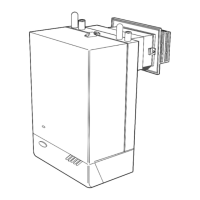
Steps for lifting the boiler onto the mounting plate and aligning the flue.

FITTING THE FLUE ASSEMBLY

DUCT LENGTHS UP TO 400 MM

Steps for fitting the flue terminal assembly for shorter duct lengths.

EXTENSION DUCTS FITTING

DUCT LENGTHS OVER 400 MM

Instructions for fitting extension ducts for longer flue lengths.

GAS CONNECTION

PRESSURE AND COCK LOCATION

Minimum gas pressure requirements and gas cock location.

ELECTRICAL CONNECTIONS AND WIRING

MAINS SUPPLY AND EARTHING

Details mains supply, earthing, and connection methods.

CONTROL BOX TERMINALS

Explains the terminals within the boiler control box.

SYSTEM WIRING DIAGRAMS

MID POSITION VALVE CONTROL

Wiring diagram for a mid-position valve system.

TWO SPRING CLOSED VALVE CONTROL

Wiring diagram for a two-spring closed valve system.

HONEYWELL C PLAN SYSTEM WIRING

Wiring diagram for a Honeywell 'C' Plan system.

FROST PROTECTION CONTROL WIRING

Wiring options for frost protection thermostats.

COMMISSIONING AND TESTING

ELECTRICAL INSTALLATION CHECKS

Procedures for ensuring electrical safety and system checks.

GAS INSTALLATION AND TESTING

Steps for gas installation inspection, testing, and purging.

INITIAL LIGHTING AND BURNER OPERATION

BOILER CONTROLS AND PILOT LIGHT

Guide to boiler controls and the procedure for lighting the pilot burner.

FITTING THE CASING

CASING SEAL AND FITMENT

Instructions for fitting the boiler casing and ensuring a proper seal.

GENERAL CHECKS AND OPERATION

BURNER AND FLAME FAILURE CHECKS

Verifies burner operation, flame failure device, and system controls.

WATER SOUNDNESS AND SETTINGS

Checks for water leaks, draining, and setting user controls.

HANDING OVER TO THE HOUSEHOLDER

USER INSTRUCTIONS AND DEMONSTRATIONS

Explaining boiler operation, controls, and user responsibilities.

SERVICING SCHEDULE AND RECOMMENDATIONS

ANNUAL SERVICING PROCEDURES

Outlines recommended servicing tasks and frequency for safe operation.

BOILER CASING REMOVAL AND CLEANING

CASING REMOVAL PROCEDURE

Steps for safely removing and refitting the boiler casing.

BURNER AND AIR BOX REMOVAL

COMPONENT REMOVAL STEPS

Detailed instructions for removing the burner and air box assembly.

CLEANING THE FLUEWAYS

COLLECTOR HOOD AND BAFFLE CLEANING

Steps for cleaning the collector hood and flue baffles.

BURNER AND PILOT ASSEMBLY CLEANING

BURNER HEAD AND INJECTOR CLEANING

Procedures for cleaning the burner head, pilot burner, and injectors.

RE-ASSEMBLY PROCEDURES

COMPONENT REASSEMBLY ORDER

Instructions for reassembling components after servicing.

PILOT BURNER SETTING AND HEAT INPUT

PILOT FLAME ADJUSTMENT AND CHECK

Guidance on checking and setting the pilot burner flame.

REPLACEMENT OF PARTS - GENERAL

ISOLATING SUPPLY AND CASING REMOVAL

Precautions before replacing any component, including isolating power.

SIGHTGLASS REPLACEMENT

SIGHTGLASS ASSEMBLY REPLACEMENT

Steps for replacing the sightglass assembly on the casing.

PIEZO UNIT REPLACEMENT

PIEZO UNIT REMOVAL AND INSTALLATION

Procedures for replacing the piezo ignition unit.

PILOT BURNER REPLACEMENT

PILOT BURNER ASSEMBLY REPLACEMENT

Steps for removing and replacing the pilot burner assembly.

SUPPRESSOR REPLACEMENT

SUPPRESSOR LEAD AND CONNECTION REPLACEMENT

Instructions for replacing the suppressor and its connections.

CONTROL THERMOSTAT REPLACEMENT

THERMOSTAT CAPILLARY AND HEAD REPLACEMENT

Steps for replacing the control thermostat and its capillary.

OVERHEAT THERMOSTAT REPLACEMENT

THERMOSTAT POCKET AND CAPILLARY ACCESS

Procedures for accessing and replacing the overheat thermostat.

SPARK ELECTRODE AND LEAD REPLACEMENT

ELECTRODE AND LEAD REPLACEMENT STEPS

Instructions for replacing the spark electrode and its lead.

THERMOCOUPLE REPLACEMENT

THERMOCOUPLE AND PILOT SHIELD REPLACEMENT

Steps for replacing the thermocouple and pilot shield.

MAIN BURNER AND INJECTOR REPLACEMENT

BURNER AND INJECTOR REMOVAL AND REFITTING

Instructions for replacing the main burner and its injector.

GAS CONTROL VALVE REPLACEMENT

VALVE, MANIFOLD AND EXTENSION REPLACEMENT

Steps for replacing the gas control valve, manifold, and extension.

COMBUSTION CHAMBER INSULATION REPLACEMENT

INSULATION PANEL REPLACEMENT

Instructions for removing and replacing combustion chamber insulation panels.

HEAT EXCHANGER REPLACEMENT

HEAT EXCHANGER ASSEMBLY REMOVAL AND REFITTING

Procedures for replacing the heat exchanger assembly.

CASING SEAL REPLACEMENT

OLD SEAL REMOVAL AND NEW SEAL FITTING

Steps for removing the old casing seal and fitting new adhesive seals.

GAS VALVE SOLENOID REPLACEMENT

SOLENOID COIL REPLACEMENT

Instructions for replacing the solenoid coil on the gas control valve.

PROGRAMMER REPLACEMENT

PROGRAMMER UNIT AND TERMINAL STRIP REPLACEMENT

Steps for replacing the programmer and its associated wiring.

BOILER ASSEMBLY EXPLODED VIEW

COMPONENT IDENTIFICATION

Exploded view showing numbered components of the boiler assembly.

BURNER AND CONTROLS EXPLODED VIEW

BURNER AND CONTROL COMPONENTS

Exploded view identifying burner and control system components.

FAULT FINDING - PILOT NOT LIGHTING

SPARK AND GAS SUPPLY CHECK

Troubleshooting steps for pilot ignition issues related to spark and gas.

FAULT FINDING - PILOT NOT STAYING LIT

THERMOCOUPLE AND GAS VALVE CHECKS

Troubleshooting for pilot flame staying lit, focusing on thermocouple.

FAULT FINDING - NO MAINS GAS

MAINS GAS AND SYSTEM CONTROL CHECKS

Troubleshooting when pilot is lit but main burner does not operate due to gas supply.

SHORT LIST OF SPARE PARTS

KEY PART NUMBERS AND DESCRIPTIONS

Lists commonly required spare parts with part numbers for ordering.

Related product manuals