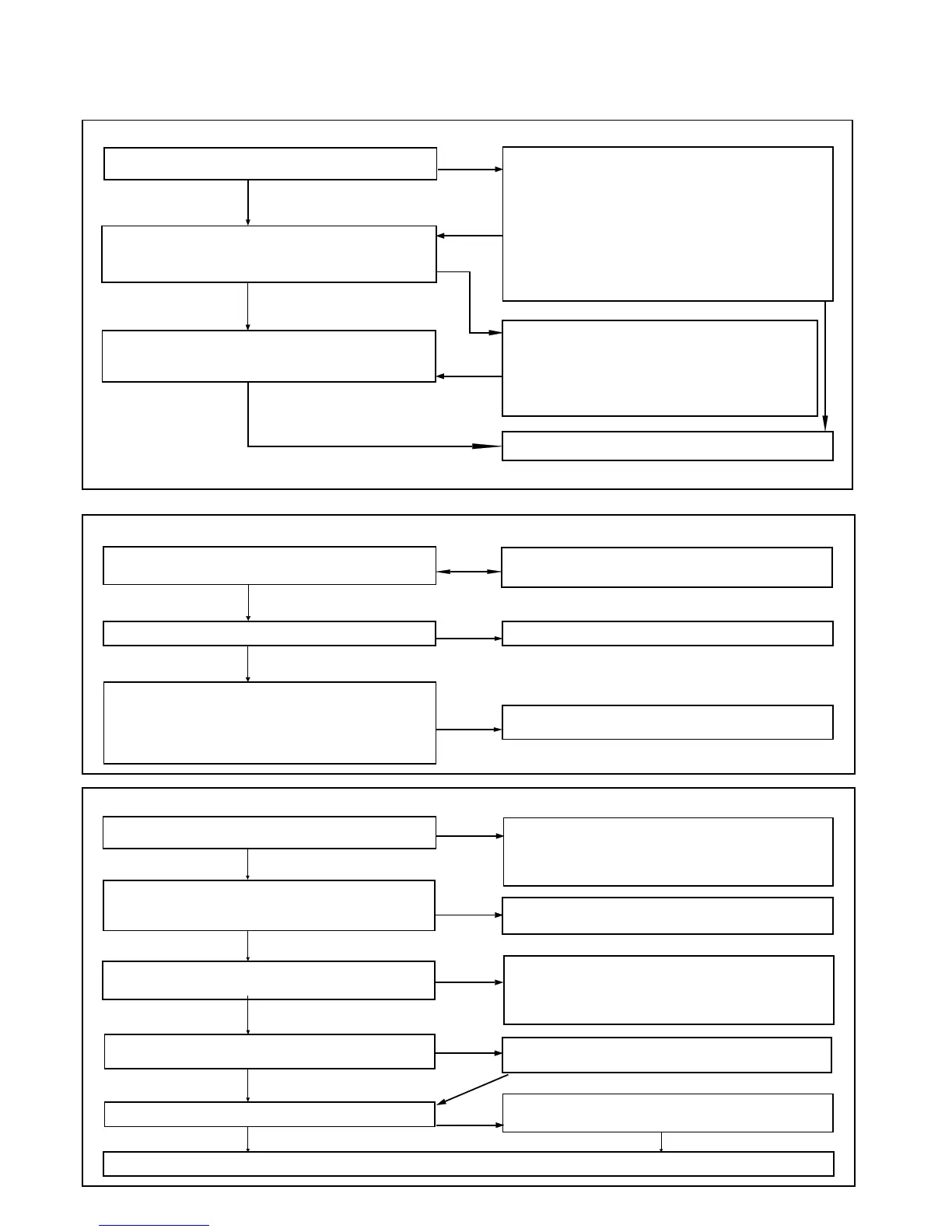
FAULT FINDING
26 PILOT WILL NOT LIGHT
NO
YES
NO
YES
27 PILOT WILL NOT STAY LIT WHEN THE GAS VALVE BUTTON IS RELEASED
Clean the contracts and reconnect securely
Replace the gas valve.
NO
NO
Check the pilot injector. Refer to Frame 11
NO
28 PILOT LIT BUT NO MAINS GAS
NO
NO
NO
NO
NO
YES
YES
Faulty piezo unit - replace
After any faults have been corrected, return all thermostatic and other controls to the previously noted settings.
22
SERVICING
Detailed instructions on the cleaning and adjustment or
placement of faulty components are contained in the 'Servicing'
section, of this publication.
NO
Before attempting any electrical fault finding ALWAYS carry out
the preliminary electrical system checks as detailed in the
Instructions for the British Gas Multimeter, or similar test
meter.
Is there a spark at the ignition electrode ?
YES
YES
Light the pilot burner with a match.
Confirm satisfactory ignition, using the piezo
unit
NO
Check thermocouple output (8-15 mV closed
circuit).Replace thermocouple if output is outside the
stated range. Reference may be made to the
British Gas Multimeter Instruction Book.
Does the pilot now stay alight ?
YES
YES
Is the connection between the thermocouple and the gas
valve clean and tight ?
Check the supply voltage, e.g., by using a Multimeter,
set on the 300 V AC range, between the L and N
terminals. Expect 240 V +/- 10%. If there is no supply
then check the fuse in the plug or other supply point.
If there is no supply, check controls. Reference may be
made to the British Gas Multimeter Instruction Book.
Check the settings of the room thermostat and the
cylinder thermostat. Check the control system.
Reference may be made to the British Gas Multimeter
Instruction Book.
Check the boiler thermostat. Reference may be made
to the British Gas Multimeter Instruction Book.
Faulty gas valve - check. Reference may be made to
the British Gas Multimeter Instruction Book.
Is there a supply voltage at the
input to the control box?
Set any CH and HW controls to the 'Continuous'
position. Is there a supply voltage between CH and N,
also between HW and N? Expect 240 V +/- 10%
YES
YES
Have you confirmed that the system controls are 'Calling
for Heat' ?
YES
Is there a supply voltage between the gas valve
terminals
?
Expect 240 V +/- 10%.
YES
Does the main burner light ?
YES
Is there gas at the pilot burner when the gas valve
button is pressed ?
Check the gap between the electrode and the pilot
burner; 3-4 mm. Refer to Frame 7.
Check the H/T lead and electrode are undamaged and
the connections are NOT close to earthed metalwork.
Check the piezo unit is operative - by holding an
earthed screwdriver approximately 3 mm from the H/T
output terminal (with the ignition lead removed) and by
operating the button.
Is there a spark across the gap ?
Allow time to purge any air present.
Check the following; the gas valve button is being
pressed fully in; there is gas pressure at the boiler
inlet; the boiler union gas cock is open; the pilot
jet is not blocked; the overheat thermostat (it fitted)
requires resetting.
Is the pilot flame the correct size (refer to Frame 7) ?
 Loading...