1. Refer to Frame 8.
2. Remove the burner and air box
assembly. Refer to Frame 3.
3. Remove the two front tie rods.
4. Remove the two side panel retaining brackets.
5. Remove the side insulation panels.
6. Remove the front and rear insulation panels.
7. Fit the new front and rear insulation panels.
SERVICING
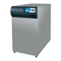
18 GAS CONTROL VALVE REPLACEMENT
1. Refer to Frame 8.
2. Remove the burner and air box assembly. Refer to Frame 3.
3. Turn off the gas supply at the service cock.
4. Remove the control box cover fixing screw and remove the
cover.
5. Pull off the two electrical connections and the earth
connection at the boiler thermostat.
20 HEAT EXCHANGER REPLACEMENT
19
Note: Refer to Frame 24 of 'Exploded Views' for illustration of
the procedure detailed below.
1. Refer to Frame 8.
2. Remove the burner and air box assembly. Refer to
Frame 3.
3. Drain the system .
4. Disconnect the water flow and return connections. If
compression fittings are used, cut the pipes both above
and below the fittings in order to allow the heat exchanger
assembly to be removed.
Remove the heat exchanger drain plug and drain the
residual water into a suitable receptacle
5. Remove the collector hood. Refer to Frame 4.
6. Remove the 4 screws retaining the flue duct and remove
the duct.
7. Remove the combustion chamber by unscrewing the nuts
retaining the side tie rods.
8. Remove the four extended nuts retaining the gas service
cock to the gas control valve.
9. Remove the control box cover and control box. Refer to
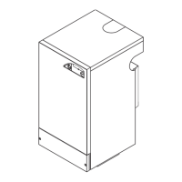
19 COMBUSTION CHAMBER
INSULATION REPLACEMENT
DETAIL OF BOILER
COMBUSTION CHAMBER
8. Fit the new side panels and retain
with the brackets and screws
previously removed.
9. Refit the front tie rods.
10. Re-assemble the rest of the
appliance in reverse order.
Combustion
chamber
Insulation panels
10. Whilst supporting the gas control valve, remove the two
screws retaining the manifold to the back panel.
11. Remove the gas control / manifold assembly.
12. Remove the four screws retaining the manifold extension
to the gas control and fit new gas control, ensuring that:
(a) The new gas control is fitted the correct way round; an
arrow is engraved on the back, indicating the direction
of gas flow.
(b) The sealing gasket is correctly fitted.
13. Re-assemble in reverse order. Note: Do NOT overtighten
the four gas cock retaining screws.
14. Replace the burner / air box assembly.
15. Replace the boiler casing. Refer to Frame 6.
16. Check the gas valve operation.
Frame 18. Unclip the thermostat capillary and remove the
phial from the pocket. Refer to Frame 13.
10. Remove the Programmer Kit (if fitted).
11. Remove the two screws retaining the manifold / gas control
valve assembly to the back panel and remove the assembly.
12. Slacken 3 turns only the four screws retaining the heat
exchanger / inter-panel assembly.
13. Lift the heat exchanger / inter-panel assembly upwards and
forwards to disengage the keyhole fixings. Pull the assembly
downwards to clear the water pipes from the back panel.
14. Remove the four rubber grommets from the top of the back
panel, to facilitate the fitting of the new heat exchanger.
15. Fit the new heat exchanger assembly, complete with its 4
pipe connections and hang it on the 4 keyhole slots and
screws. Retighten the 4 screws.
16. Replace the 4 rubber grommets in order to seal the gap
between the water pipes and the back panel.
17. Re-assemble in reverse order. Note: Do NOT overtighten
the four gas cock retaining screws.
18. Remake all water connections, ensuring that the
compression fittings ( if used ) are correctly refitted.
19. Fully test all functions, including water and gas soundness.
see note 7
Manifold, see note 10
Gas control
valve
Gas cock,
see note 3
Manifold extension,
see note 12
Boiler
thermostat
see note 4
Control
box
6. Remove the control
box fixing screw, situated
behind the suppressor.
7. Withdraw and suspend the control box. Pull off the gas
valve solenoid connections and disconnect the earth
connection at the solenoid. Pull off the 2 connections at
the piezo generator.
8. Withdraw the thermostat phial from its pocket (refer to
Frame 13).
9. Remove the four M4 extended screws retaining the gas
service cock to the gas control.
REPLACEMENT OF PARTS
Note: Refer also to Frame 25 'Exploded Views' for
illustration of the procedure detailed below.
 Loading...