11
78
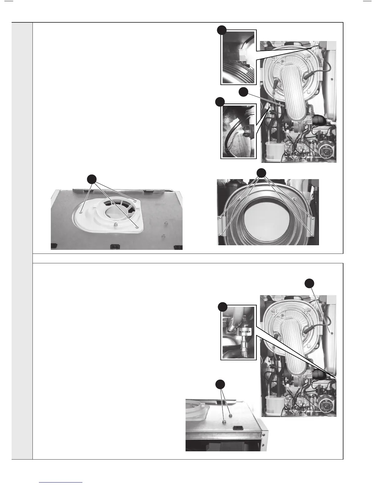
hEAT ExChANgER REpLACEMENT
79
ExpANsION VEssEL REChARgINg AND REpLACEMENT
1. Refer to Frames 45 & 46.
2. Refer to Frame 53.
3. Close the isolating service valves and drain the (CH) boiler. Refer to
Frame 67.
4. Remove the Burner & Fan assembly. Refer to Frame 47.
5. Remove the securing clips to disconnect the ow and return pipes
below the heat exchanger.
6. Disconnect the condensate pipe from the sump
7. Disconnect the DRYFIRE ONE TIME sensor lead.
8. Remove the horseshoe bracket and lift up the ue turret.
9. Remove the securing screws and disconnect the ue outlet
10. Remove the 4 screws securing the heat exchanger xing brackets.
11. Remove the heat exchanger forwards, lifting to clear the ow and
return pipes
12. Ret in reverse order. Ensure all wires and harnesses are in their
correct position in order to prevent damage to them.
13. Open the isolating valves and rell the CH system. Refer to Frame 67.
14. Check the operation of the boiler. Refer to Frames 33-36.
Recharging:
1. Refer to Frames 45 & 46.
2. Refer to Frame 53.
3. Remove the charge point cover.
4. Recharge the tank pressure to 0.75bar
5. Ret in reverse order
6. Check the operat ion of the boiler. Refer to Frames 33-36.
Replacement:
7. Refer to Frame 45 & 46.
8. Refer to Frame 53.
9. Close the isolating service valves and drain the (CH) boiler
10. Remove the clip securing the exible connecting hose and
disconnect.
11. Remove the two securing screws from the top of the casing
at the same time holding the ignitor bracket to prevent
movement.
12. Hold the expansion vessel and move the ignition assembly
bracket carefully to one side.
13. Pull the bottom of the expansion vessel forward, when free
pull vessel downwards and remove.
14. Ret in reverse order.
15. Open the isolating valves and rell the CH system.
16. Check the operation of the boiler. Refer to Frames 33-36.
5
10
7
10
6
3
9
sERVICINg

 Loading...


