20
DD48 Series Display Units
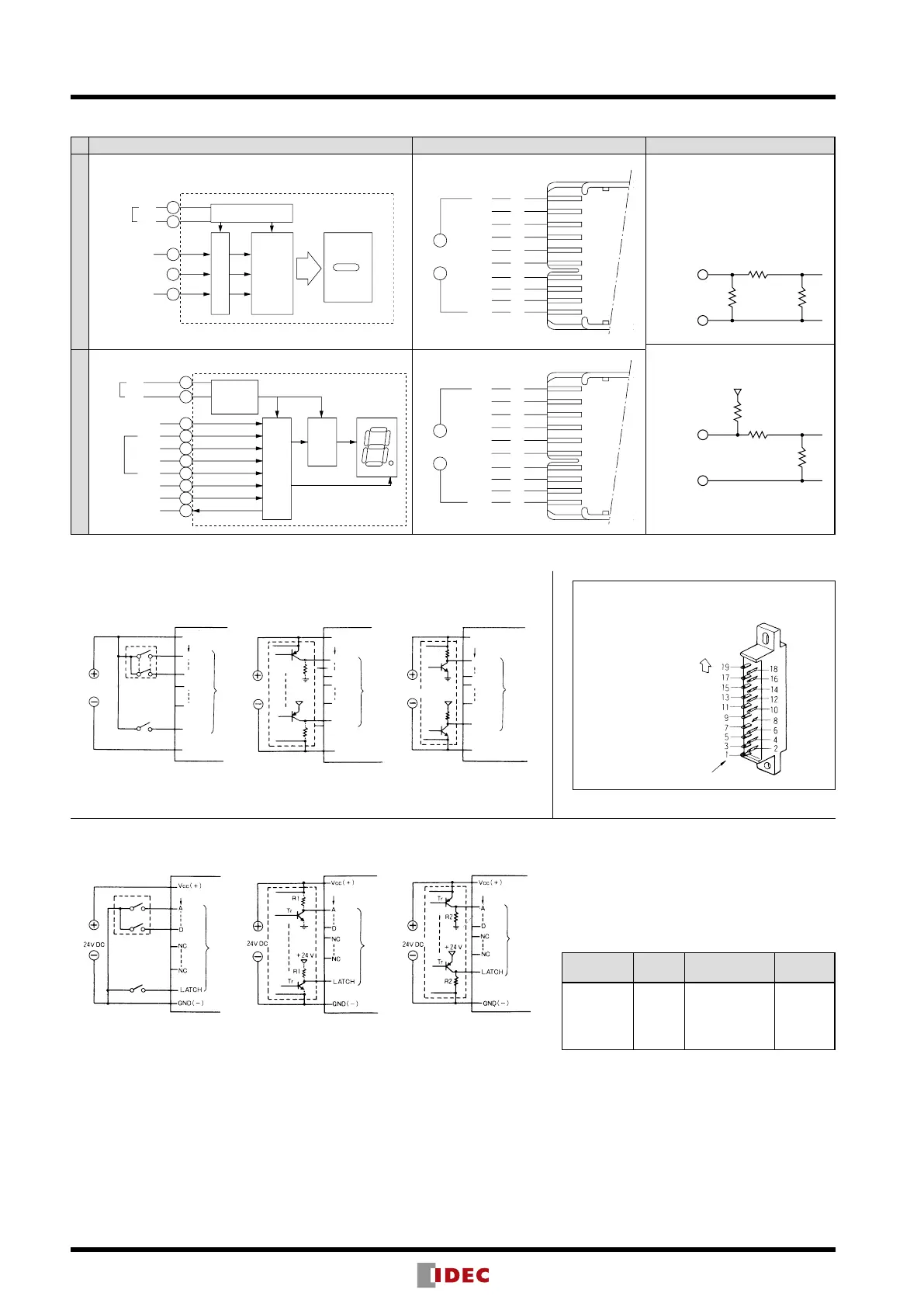
Terminal Connection
Connection Diagram Terminal Arrangement Internal Input Circuit
Binary Display Unit
Positive Logic
200 kΩ
12 kΩ
Negative Logic
200 kΩ
200 kΩ
12 kΩ
Decimal Display Unit
(Name)
(Terminal No.)
Power
Vcc
GND
BL
(–)
Latch
19
1
7
9
11
Regulating Circuit
Decoder
Input Circuit
Vcc
NC
NC
NC
(−)
Latch
BL
NC
NC
GND
19
17
15
13
11
9
7
5
3
1
-
(Name)
(Terminal No.)
+
Vcc
GND
19
1
9
17
15
13
11
7
5
3
Latch
A(2 )
B(2 )
C(2 )
D(2 )
DP
RBI
RBO
0
1
2
3
(Name)
(Terminal No.)
Power
Data
Input
Regulating
Circuit
Decoder
Input Circuit
Vcc
A (2 )
Latch
DP
RBI
RBO
GND
19
17
15
13
11
9
7
5
3
1
0
B (2 )
1
C (2 )
2
D (2 )
3
-
(Name)
(Terminal No.)
+
Connector Terminal No.
(Binary/Decimal Display Unit Compatible)
Connector Terminal No.
UP marking side
Power
24V DC
Power
24V DC
24V DC
Tr
R1
Tr
R1
+24V
Tr
R1
Tr
R1
+24V
Power
Decimal
Vcc(+)
A
D
NC
NC
LATCH
GND(—)
Vcc(+)
A
D
NC
NC
LATCH
GND(—)
Vcc(+)
A
D
NC
NC
LATCH
GND(—)
Decimal
Decimal
Data
Input
Data
Input
Data
Input
When Tr is on,
output goes to H.
When Tr is off,
output goes to H.
External Wiring
Positive Logic
[Contact Input (Digital Switch)] [Transistor Input]
Power
Power
Power
Decimal
Decimal
Decimal
Data
Input
Data
Input
Data
Input
When Tr is on,
output goes to L.
When Tr is off,
output goes to L.
Negative Logic
[Contact Input (Digital Switch)] [Transistor Input]
Note: When connecting pull-up or pull-down resistors to
the external circuit, refer to the following table.
External
Power Supply
Type R1 R2
24V DC
Binary/
Decimal
2.2 kΩ to 8.2 kΩ
(1/2W) (1/4W)
1 kΩ (1W)