7
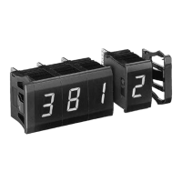
DD3S Series Display Units
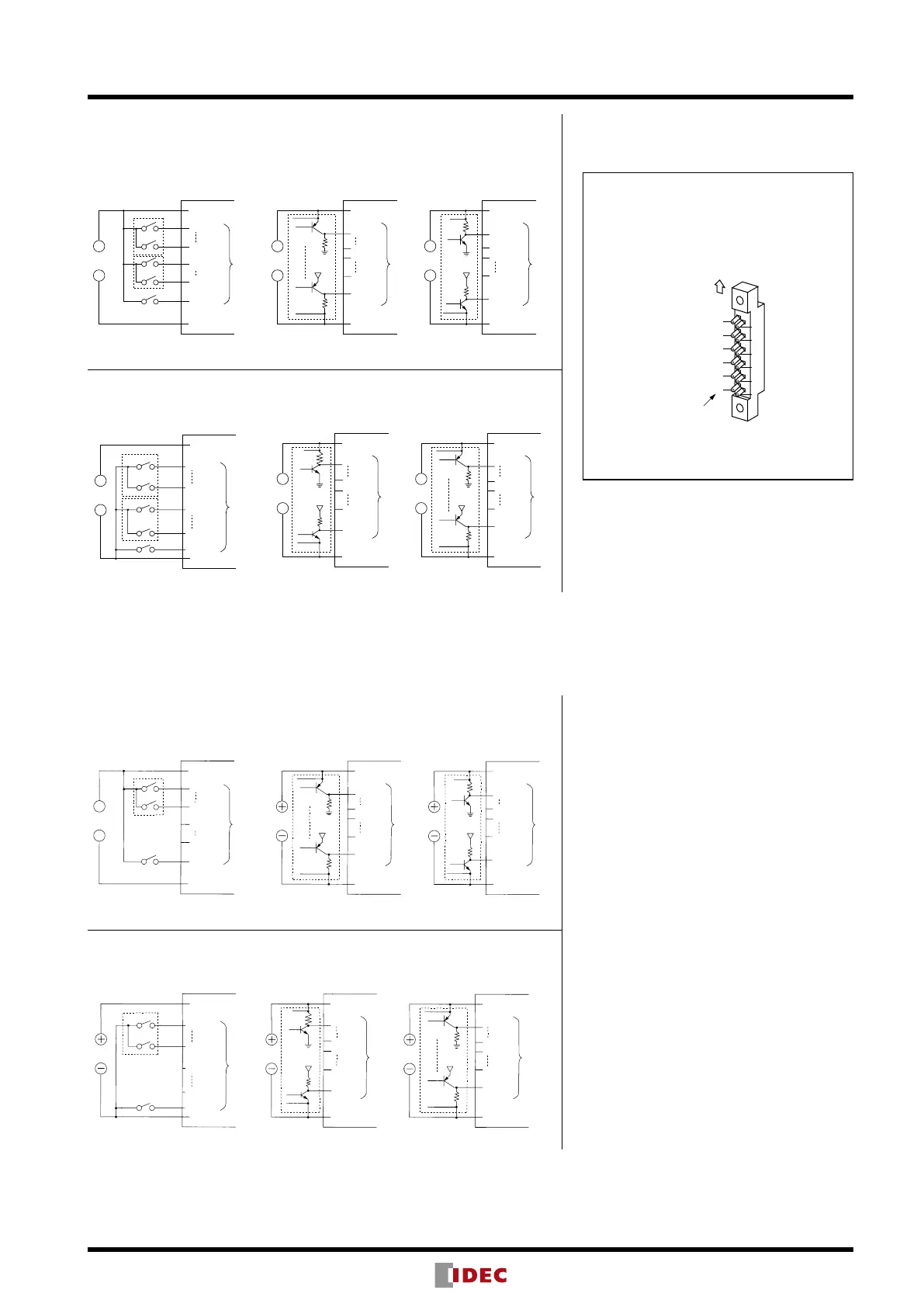
External Wiring
Binary/Decimal/Hexadecimal/Extra Decimal Display Units
Positive Logic
[Contact Input (Digital Switch)] [Transistor Input]
A
D
NC
NC
Latch
−
Vcc (+)
GND (–)
Input
+
A
D
NC
NC
Latch
Latch
Tr
Tr
R1
Tr
R2
Tr
R2
R1
A
D
NC
NC
+V+V
−
Vcc (+)
GND (–)
Data
Input
Vcc (+)
GND (–)
Data
Input
+
Power
−
+
When Tr is on, output goes to H. When Tr is off, output goes to H.
Negative Logic
[Contact Input (Digital Switch)] [Transistor Input]
A
D
NC
NC
Latch
−
Vcc (+)
GND (–)
Input
+
A
D
NC
NC
Latch
Tr
Tr
R3
Tr
R1
Tr
R1
R3
+V+V
A
D
NC
NC
Latch
−
Vcc (+)
GND (–)
Data
Input
Vcc (+)
GND (–)
+
Power
−
+
When Tr is on, output goes to L. When Tr is off, output goes to L.
Note: When connecting pull-up or pull-down resistors to the external circuit, refer to the resistor
values shown below:
R1: 2.2 kΩ (1/2W) to 10 kΩ (1/4W)
R2: 1 kΩ (1W) to 2.2 kΩ (1/2W)
R3: 1 kΩ (1W)
Character Display Units
Positive Logic
[Contact Input (Digital Switch)] [Transistor Input]
Power
Tr
Tr
R1
R1
+V
+V
When Tr is on, output goes to H. When Tr is off, output goes to H.
Power
R2
R2
Tr
Tr
−
Vcc (+)
GND (–)
Vcc (+)
GND (–)
Vcc (+)
GND (–)
Data
Input
Data
Input
Input
+
Latch
D0
D7
NC
NC
Latch
Latch
D0
D7
NC
NC
D0
D7
NC
NC
Negative Logic
[Contact Input (Digital Switch)] [Transistor Input]
Power Power
When Tr is on, output goes to L. When Tr is off, output goes to L.
Vcc (+)
GND (–)
Vcc (+)
GND (–)
Vcc (+)
GND (–)
Data
Input
Input
Data
Input
Latch
Latch
Latch
D0
D7
NC
NC
D0
Tr
R1
Tr
R1
D7
NC
NC
D0
D7
+V+V
Tr
R3
Tr
NC
NC
Note: When connecting pull-up or pull-down resistors to the external circuit, refer to the resistor
values shown below:
R1: 2.2 kΩ (1/2W) to 10 kΩ (1/4W)
R2: 1 kΩ (1W) to 2.2 kΩ (1/2W)
R3: 1 kΩ (1W)
12
10
8
6
4
2
11
9
7
5
3
1
UP Making Side
Connector
Terminal No.
(DMC-1)
Connector Terminal No.