30
DD96 Series Display Units
(H)
(L)
(H)
(L)
(H)
(L)
(H)
(L)
(H)
(L)
1
2
4
8
Binary-
coded
Input
Latch Input
Display
Character
Maintains
display
Maintains
display
“1” “2” “3” “4” “5” “6” “7” “8” “9”
“1” “2” “5” “6” “8” “9”
T1 T2 T3
(H)
(L)
Latch Input
Binarycoded
Input
(Data Input)
Maintain Maintain
Data is
read.
T1 ≥ 0 ms
T2 ≥ 5 ms
T3 ≥ 5 ms
(H)
(L)
(H)
(L)
(H)
(L)
(H)
(L)
4th
Digit
4th
3rd
2nd
1st
3rd
Digit
2nd
Digit
1st
Digit
Binary-coded
Input
(Data Input)
Latch
Input
Display Unit
4th Digit
Data
3rd Digit
Data
2nd Digit
Data
1st Digit
Data
Maintain Maintain
Maintain Maintain
Maintain Maintain
Maintain Maintain
Display (Example)
4th
Digit
Latch
Latch
Latch
Latch
Binary-coded Input
(Data Input)
(Latch Input)
3rd
Digit
2nd
Digit
1st
Digit
3rd
2nd
4th
1st
Latch Input
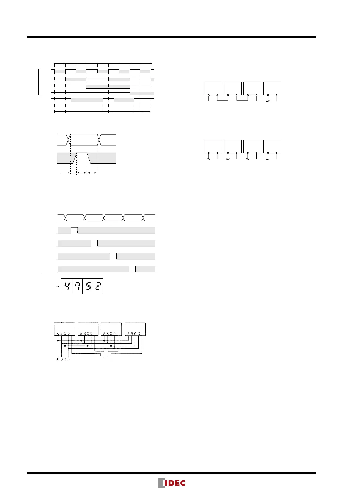
Latch Operation
Latch Input Timing Chart
Application of Latch Function
Note: If the data input is changed in the period of T2, the display will
change.
Block Diagram
Instructions
1. A red lter is not provided for the front of the DD96 series rear
mount display unit.
2. When cleaning the surface of the lter and housing, use a soft
cloth. Do not use thinner or acid to clean the surface
3. When the display unit is mounted in a panel cut-out, do not
place a metal object or power line within 40 mm from the end
of the connecter terminals at the rear of the display unit.
4. If the display unit is subjected to voltage surges, install a surge
suppressor in the power line.
5. Use shielded cable or metal conduit for the input line. Run the
input wiring as far away as possible from high-voltage and
motor lines. Make the input line as short as possible.
6. When using display units in environments where a large
amount of electrostatic noise is generated, such as where
molding materials, powders, or uids are transferred through
pipe lines, keep the display units as far away as possible from
electrostatic sources.
7. Avoid using the display unit in a place where excessive and
frequent vibration or impact may occur.
8. Avoid using the display unit in a place where it is exposed to
corrosive gas, water or oil splashes, dust or direct sunlight, or
in a place where organic solvents are used.
9. The lter is made of polycarbonate. Make sure that machine oil
does not touch the lter.
10. If the Latch input is on when the DD96 is powered up, the
data input cannot be read correctly or wrong data may be
maintained. Do not turn on the Latch input for 0.5 sec after the
DD96 is powered up.
11. When the DD96 is powered up, an inrush current of 0.4A (10
ms maximum) ows through the internal power supply circuit.
Select an external power supply of suf cient capacity, taking
inrush current into consideration.
12. When connecting a pull-up or pull-down resistor to the input
terminals, ensure compatibility with the input resistor in the
DD96 internal circuit.
Connection to Terminals BI and BO
[Ex. 1]
By connecting as shown below, 0 is displayed when input
is 0000 and 25 is displayed when input is 0025, eliminating
unnecessary 0s in upper digits.
BI BO BI BO BI BO BI BO
4th
Digit
Open Open Open
3rd
Digit
2nd
Digit
1st
Digit
[Ex. 2]
By connecting as shown below, 0000 is displayed when
input is 0000 and 0025 is displayed when input is 0025,
with all 0s in upper digits displayed.
BI BO BI BO BI BO BI BO
4th
Digit
Open Open Open Open
3rd
Digit
2nd
Digit
1st
Digit
Notes:
1. Use BO output only for connection to BI input in the lower digit as shown
in Ex. 1 above. Do not use the BO for other purposes.
2. When zero blanking is not required, maintain BI input in level L.