Part 2 - Conguration
70
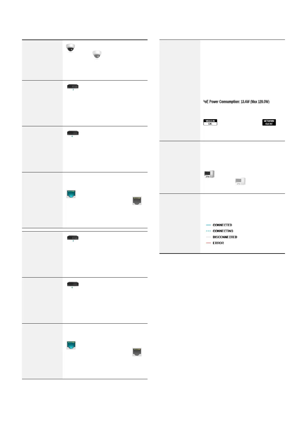
Camera
Connection
indicates the camera is
connected.
indicates the
camera is not connected. Clicking
the image displays the camera's
channel number.
Network Switch
indicates a network switch
is connected to the LAN port and
shows how many cameras are
connected. Clicking the image
displays the camera’s channel
number.
Video Encoder
indicates a video encoder
is connected to the LAN port and
shows how many cameras are
connected. Clicking the image
displays the camera’s channel
number.
LAN Port Link
indicates a camera or a
network switch is connected.
indicates neither is connected.
Power
Consumption
If receiving power from the NVR,
the actual amount of power
consumed by each camera is
indicated under each camera icon.
Total power consumption is shown
at the top of the screen in the
following format:
[
]
Ports 1 through 8 support PoE.
(VIDEO IN Ext.) and
(NETWORK CLIENT) ports do not
support PoE.
Number of
Connected
Clients
Indicates whether there are clients
connected to the NVR via an
external network and how many
clients are connected.
indicates at least one client
is connected.
indicates no
client is connected.
Network
Connection
Info
Indicates network connection
statuses (connected, connecting,
disconnected, and connection
error) using following lines:
 Loading...