EasyManuals Logo

IFM Electronic PY995 Series User Manual

IFM Electronic PY995 Series
To Next Page IconTo Next Page
To Previous Page IconTo Previous Page
Page #19 background imageLoading...
Page #19 background image
Before mounting and removing the sensor, make sure that no
pressure is applied to the system.
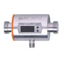
Mount the pressure sensor on a G¾ process connection.
The unit must be connected by a suitably qualified electrician.
The national and international regulations for the installation of
electrical equipment must be observed.
Voltage supply to EN50178, SELV, PELV.
The device shall be supplied from an isolating transformer having a
secondary Listed fuse rated as noted in the following table.
The Sensor shall be connected only by using any R/C (CYJV2) cord,
having suitable ratings.
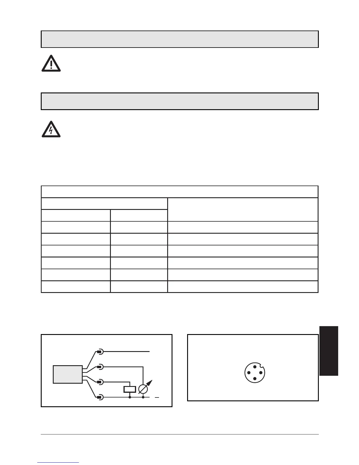
Disconnect power before connecting the unit as follows:
19
ENGLISH
Installation
Electrical connection
Core colours of ifm sockets:
1 = BN (brown), 2 = WH (white), 3 = BU (blue), 4 = BK (black).
3
1
4
2
Connector view (sensor)
L
L
+
3
4
2
1
BU
BK
WH
BN
Overcurrent protection
Control-circuit wire size
Maximum protective device rating
Ampere
AWG (mm
2
)
26 (0.13) 1
24 (0.20) 2
22 (0.32) 3
20 (0.52) 5
18 (0.82) 7
16 (1.3 ) 10

Questions and Answers:

Question and Answer IconNeed help?

Do you have a question about the IFM Electronic PY995 Series and is the answer not in the manual?

IFM Electronic PY995 Series Specifications

General IconGeneral
BrandIFM Electronic
ModelPY995 Series
CategoryAccessories
LanguageEnglish

Related product manuals