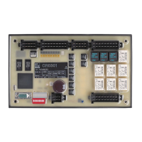
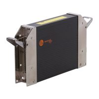
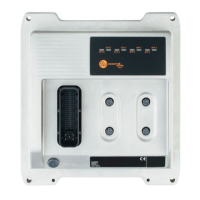
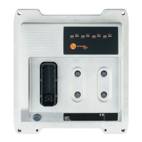
ecomatController CR720S/CR721S
10
To ensure the protection of the device against electrical interference and the
safe function of the device, the housing must be connected to the ground /
body of the vehicle in the shortest possible way�
► Connect the device to the ground of the vehicle using the M4 self-tapping
screw (included)�
5.3 Fuses
► The individual electric circuits must be protected in order to protect the whole
system�
Connector Designation Potential Pin no. Fuse
Connector A Supply voltage sensors/module VBB
30
30 ≤ 2 A time-
lag
Supply voltage sensors/module VBB
15
15 ≤ 2 A time-
lag
Supply voltage output group 0 VBB
0
04 ≤ 15 A
Supply voltage output group 1 VBB
1
03 ≤ 15 A
Supply voltage output group 2 VBB
2
01 ≤ 15 A
Connector B Supply voltage output group 3 VBB
3
04 ≤ 15 A
Supply voltage output group 4 VBB
4
03 ≤ 15 A
Supply voltage output group 5 VBB
5
01 ≤ 15 A
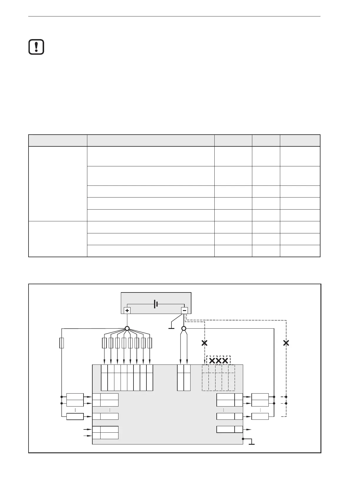
5.4 Laying the supply and signal cables
supply
output
nn
output
nn
output
nn
controller
VBB
30
nn
VBB
15
nn
VBB
0
nn
VBB
1
nn
VBB
2
nn
VBB
3
nn
VBB
4
nn
VBB
5
nn
GND
SYS
nn
GND
1...4
GND
SYS
GND
RES
GND
ANA
GND
OVA
GND
1...4
nn
input
nn
input
nn
GND
ANA
nn
nn
input
nn
sensor
sensor
sensor
load
load
load
GND
OVA
Shield
nn
nn
nn
nn
nn
nn
GND
RES
Connection of the supply and signal cables (X = not permitted), example CR721S