UK
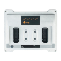
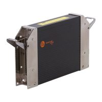
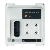
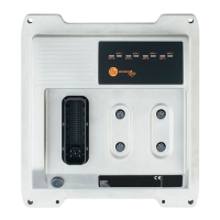
ecomatController CR720S/CR721S
11
WARNING
The linking of connections in the plug is not permitted and can affect the safety of
operators and machinery�
► Basically all supply and signal cables must be laid separately�
► Connect supply and ground cables to the controller and the sensors/actuators
via the respective common star point�
If a prewired connection cable is used, remove the cores with unused signal
inputs and outputs�
Unused cores, in particular core loops, lead to interference coupling that
can influence the connected controller�
In case of signal failures, operate inputs with shielded cables� Connect the
shields to the shield connection on one side�
VBB
0
must be connected in order to protect the controller against load dump
WARNING
If VBB
0
is not connected, this can affect the safety of operators and
machinery�
Abbreviation Input / output type
A
B
H
B
L
FRQ
L/H
PWM
H
PWM
L
PWM
I
R
Analogue
Binary high side (CSO)
Binary low side (CSI)
Frequency/pulse inputs configurable low side (CSI) / high side (CSO)
Pulse width modulation high side (CSO)
Pulse width modulation low side (CSI)
Pulse width modulation current-controlled
Resistor input
5.4.1 GND connections
► Connect the GND
1���4
and GND
SYS
connectors individually to the common GND
star point�
► Connect the shield connection of the housing to the ground / body of the
vehicle in the shortest possible way�
WARNING
Do not connect the GND
ANA
, GND
RES
and GND
OVA
connectors to the common
GND star point, but to the GND of the signal source or of the connected device�