UK
ecomatController CR720S/CR721S
17
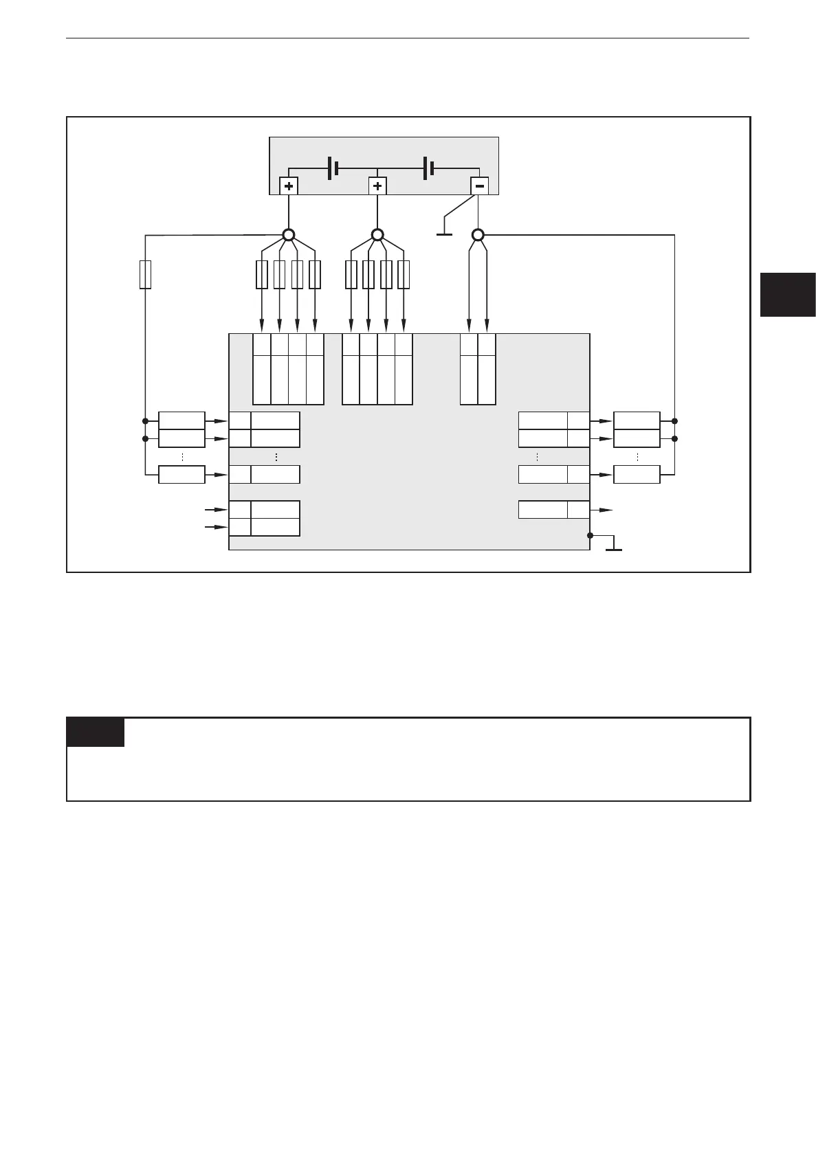
5.10 Mixed operation (12 V / 24 V)
supply
output
nn
output
nn
output
nn
controller
VBB
30
nn
VBB
15
nn
VBB
0
nn
VBB
1
nn
VBB
2
nn
VBB
3
nn
VBB
4
nn
VBB
5
nn
GND
SYS
nn
GND
1...4
nn
input
24 V 12V
nn
input
nn
GND
ANA
nn
nn
input
nn
sensor
sensor
sensor
load
load
load
GND
OVA
Shield
nn
GND
RES
Example connection to 24 V and 12 V power supply combined
The operation of the output groups is possible with different supply voltages�
► VBB
0
, VBB
30
and VBB
15
must be connected at the common star point�
5.11 Connection technology
NOTE
Only connect the 81-pole connectors when the supply voltage is disconnected�
"Hot plugging" is not permitted�
► Use twisted-pair cables for the CAN connection�
► Use a min� category 5 (Cat 5) cable for the Ethernet connection�
The RS-232 interface serves only as a service interface (e�g� for firmware
updates)�