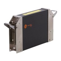
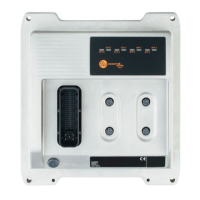
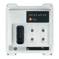
ecomatController CR720S/CR721S
26
ifm electronic gmbh ● Friedrichstraße 1 ● 45128 Essen We reserve the right to make technical alterations without prior notice! 22 Nov� 2017CR720S / page 7
CR720S Connectors A and B / input characteristics
Connector A:
IN0300... 0301
IN0800... 0801
Connector B:
IN1300... 1303
Resolution 12 bits
Input frequency < 330 Hz
Impedance ≤ 3.2 k Ω
Range diagnostics confi gurable minimum and maximum values
for the measuring range to detect short circuit
to VBB and short circuit to GND / wire break
Digital inputs 2-wire sensor
(IN DIGITAL-B)
Digital input (B
L
)
Input resistance 3.2 k Ω
Switch-on level
> 0�7 VBB
30
Switch-off level < 0�3 VBB
30
Accuracy B
L
± 1 %
Range diagnostics min - max� 1 V / 0�95 VBB
30
(default)
Observe the notes on the confi guration of the inputs/outputs!
(Programming manual "ecomatController CR720S")
Abbreviations A
B
H
B
L
FRQ
L/H
PWM
H
PWM
L
PWM
I
R
VBB
0���3
VBB
30
analogue
binary high side (CSO)
binary low side (CSI)
frequency/pulse inputs confi gurable low side (CSI) / high side (CSO)
pulse-width modulation high side (CSO)
pulse-width modulation low side (CSI)
pulse-width modulation current-controlled
resistance input
supply output group via semiconductor switch
supply sensors/module