27
When the unit is supplied with operating voltage for the first time, the
probe length, the medium to be detected and the type of probe used must
be entered. Only then is the unit ready for operation (→ 10.2).
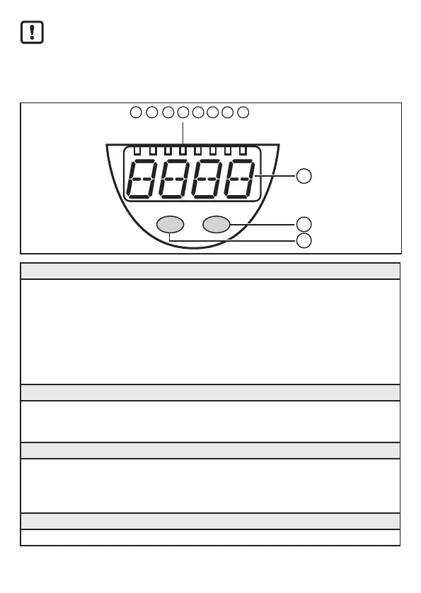
8 Operating and display elements
10
9
11
Mode/Enter Set
cm
1
inch
%
2
OUT2
7
OUT1
83 4 5 6
OUT3
OUT4
1 to 8: Indicator LEDs
- LED 1: green = indication of the level in cm�
- LED 2: green = indication of the level in inch�
- LED 3: green = indication of the level in % of the final value of the measuring range�
- LED 4: not used�
- LED 5: yellow = output 4 is switched�
- LED 6: yellow = output 3 is switched�
- LED 7: yellow = output 2 is switched�
- LED 8: yellow = output 1 is switched�
9: Alphanumeric display, 4 digits
- Indication of the current level�
- Operation and fault indication�
- Indication of the parameters and parameter values�
10: Set button
- Setting of the parameter values (scrolling by holding pressed; incremental by pressing
once)�
- Change between cm/inch indication and percent indication in the normal operating mode
(Run mode)�
11: Mode/Enter button
- Selection of the parameters and acknowledgement of the parameter values�