34
10.3 Configuration of the display
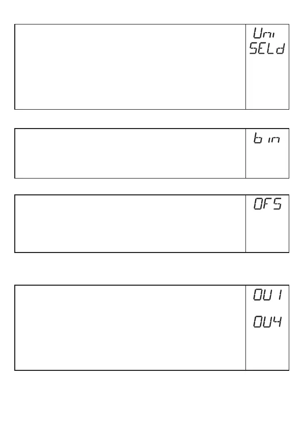
► Select [Uni] and set the unit of measurement: [cm], [inch]�
Factory setting: cm�
► Select [SELd] and set type of indication:
- [L] = The level is indicated in cm or inch�
- [L%] = The level is indicated in percent of the final value of the
measuring range�
- [OFF ] = The display is switched off in the operating mode� When one
of the buttons is pressed, the current measured value is displayed for
30 s� The LEDs remain active even if the display is deactivated�
10.4 Selecting the evaluation mode
► [Select [bin] and set the mode:
[OFF] = switching mode (= on delivery),
[on] = binary mode�
The switching parameters SPx, rPx, OUx and drx are not available in the
binary mode�
10.5 Offset setting
► Select [OFS] and enter the distance between bottom of the tank and
lower edge of the probe�
Afterwards, display and switch points refer to the real level� Factory setting:
[OFS] = 0�
Note: Set [OFS] before setting the switching limits (SPx/FHx, rPx/FLx)�
Otherwise, the switching limits shift by the value of the set offset�
10.6 Setting of output signals
10.6.1 Setting of the output function
► Select [OU1] ��� [OU4] and set the switching function:
[Hno] = hysteresis function/NO,
[Hnc] = hysteresis function/NC,
[Fno] = window function/NO,
[Fnc] = window function/NC�
Note: If the upper switch point is used as an overflow protection, the setting
OUx = Hnc (NC function) is recommended� The principle of normally
closed operation ensures that wire break or cable break is also
detected�
���