robolink
®
Joint kit – Documentation (#4; 2016-12)
igus
®
GmbH | Martin Raak | Tel. +49 (0)2203 9649 409 | mraak@igus.de 9
DOF
Fig.
Version
[mm]
(Stand.)
x1*)
[mm]
x2*)
[mm]
x3*)
[mm]
x4*)
[mm]
[mm]
*)
[gr]
*)
load [N]
*)
load [N]
*)**)
5
17
RL-T10101(-E)
100 236
236
134
-
606
1.020
30 12
17
RL-T101P1P1(-E)
100 236
207
207
134
784
1.170
18 5
17
RL-B101P1(-E)
100 252
207
134
-
593
1.960
30 9
6
18
RL-B10101(-E)
100 252
236
134
-
622
2.060
29 8
18
RL-B10301(-E)
100 282
236
134
-
652
2.115
28 7,5
*) only applies to geometric configurations with standard tube length = 100mm
**) at 30 RPMs and 0.1 sec. ramp time
Table 1: Specification for articulated arms with 1-6 DOF
All articulated arms can be optionally equipped with angle sensors (=> Section - Angle
sensors). The shown end-plates (for rotating joints) or end-flanges (for 2 axes and swivel
joints) are not part of the delivery scope, but can be ordered as accessories.
When the articulated arm is equipped with a rotating joint, RL-50-TL1, in the first position,
the assembled wires already exit the arm in pairs.
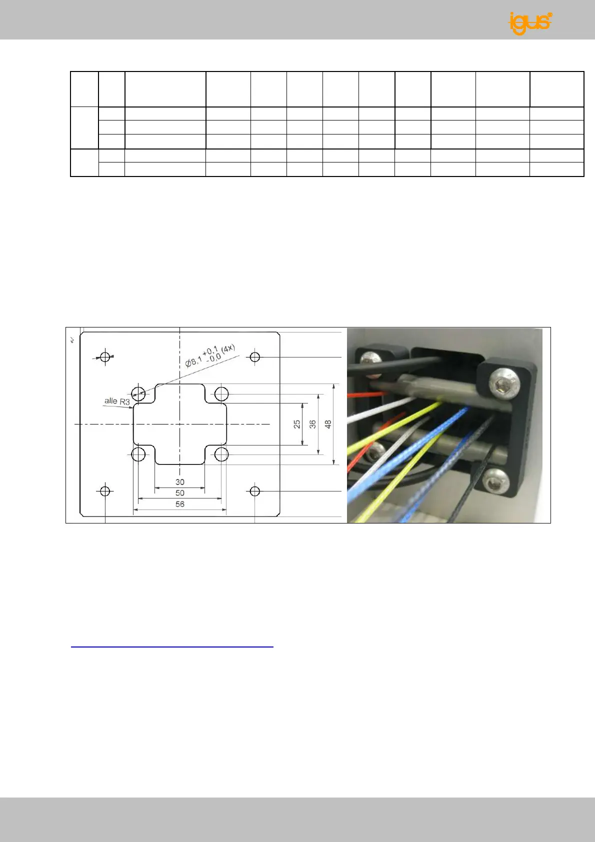
Fig. 19: Dimensioned drawing for an optional mounting plate for the rotating joint, rotating
joint view from below
When the articulated arm is equipped with a 2 axes or a swivel joint in the first position,
the use of a wire splitting unit (RL-WSU8-001) is generally recommended starting at 3
DOF for a controlled distribution of the drive wires.
The 3D STEP data for all articulated arms is available for download at:
www.igus.de/robolink/support&service.